


This socket supports uFCPGA & uFCBGA package CPU, which is the latest CPU
package developed by Intel. Other forms of CPU package are impossible to be
fitted in.
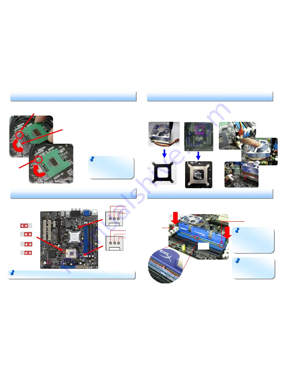
1.
Unscrew socket screw counter-
clockwise.
2.
Locate Pin 1 in the socket and look for
a golden arrow on the CPU upper
interface. Match Pin 1 and golden
arrow. Then insert the CPU into the
socket.
3.
Lock the socket screw clockwise to
fasten CPU.
Please mechanically open up AOpen proprietary CPU cooler and first relocated the
bottom fan plate and place it to the back of CPU where the motherboard is located.
The place the fan facing forward, insert the power plug to the power source and
lock the part that stick out from the bottom plate of the fan tightly.
Adjust the FSB speed of the jumper according to the CPU specification.
3. Installing Memory Modules
2. Adjusting FSB by jumper
1. Installing CPU
DIMM slots are designed in black which are very easy to recognize. Insert the
module straight down to the DIMM slot with both hands and press down firmly until
the DIMM module is securely in place.
4. Installing Memory Modules
Note:
If you do not
match the CPU socket Pin 1
and CPU golden arrow well,
you may damage the CPU.
Note:
The tabs of the
DIMM slot will close-up to
hold the DIMM in place
when the DIMM touches
the slot’s bottom.
Note:
Some CPU fans do not have sensor pin so they cannot support fan monitoring.
Golden arrow
Socket Pin 1
Socket Screw
Tab
Key
Pin 1
STEP 1
STEP 2
STEP 3
+12V
Sensor
GND
+12V
Sensor
GND
1
Front Side Bus (FSB)
1
1
1
Note:
If you only have
one DDR DIMM, please
plug it from the first DIMM
slot that is near CPU
400Mhz
JP78
JP90
533Mhz
(Default)
JP78
JP90


