21 |
ANYLOAD 805HP Handheld Digital Weighing Indicator User’s Manual (V1710)
ANYLOAD 805HP Handheld Digital Weighing Indicator User’s Manual (V1710)
| 22
2. When load weight exceeds the overload alarm set value, the background light
flashes (if background light is enabled), the panel shows (warning signs), the
display flashes, shows the error message , and the buzzer warns
3. If, overload weight exceeds the historical maximum overload weight, the
historical maximum overload weight will be updated. You can find the maximum
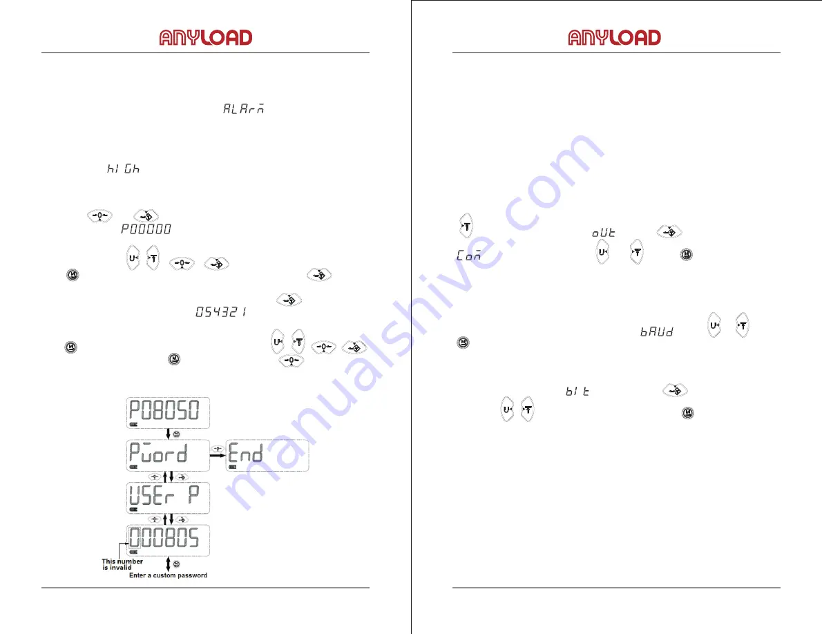
Press the , key, and hold for 1 second, indicator pops up the
Press the arrow keys , , , Enter the password 08050, then
press key, display shows the password menu (PWORD). Press to enter.
The first parameter is the user’s password (USER P), press to enter, display
the current password, for example . Note that the password is
effective only within five-digital, one hundred thousand digits will be discarded.
Press key to start modification, press the arrow keys , , ,
enter the new password, press key again to save, press key to return to
intermittently.
overload in the menu.
8.3 Modify Password
password interface .
the previous menu. Details are as follows:
9. Communication
The 805HP indicator has two ways in communicating to the scale:
9.1 RS232 Communication
length is 15 meters and beyond this length may lead to a high error rate.
I. Serial communication baud rate
to confirm selection.
II. Data frame format
1
The indicator has a standard RS-232 serial output interface to connect to large
screen monitors, computers or other peripherals. Its effective connection cable
To turn on / off serial communication, enter the configuration menu and press
until the indicator shows . Press to enter the submenu
and select on / off with , . Press to confirm selection.
Serial communication baud rates 1200bps, 2400bps, 4800bps, 9600bps are
available. The baud rate is set in the submenu using , . Press
Data frame format is set in submenu. Press to enter the submenu
and use the , to select your desired format. Press to confirm selection.
Serial output format can be configured as 8N1 / 8O1 / 8E1. 8N1 means 1 start bit,
8 data bits, 1 stop bit, and no parity. 8O1 means 1 start bit, 8 data bits, 1 stop bit,
and odd parity. 8E1 means 1 start bit, 8 data bits, 1 stop bit, even parity.
®
®


