6 Operation
C58IB004EN-D
29
To
fill the sample stage with gas
, proceed as fol-
lows:
1. Feed a suitable gas hose through the cabinet of
the diffractometer and connect it to the
flange (DN16KF) on the connection device of
the DHS 1100 (refer to
the Gas Supply/Vacuum Equipment
).
2. Connect the other end of the gas hose to the
pressure reducer/regulator of your gas supply.
3. In order to remove the air from the sample
stage, apply a pressure of approx. 0.5 bar. This
opens the pressure relief valve and the instru-
ment is flushed with the non-reactive gas.
4. After a few minutes, depending on the permitted
amount of residual air, reduce the pressure to
0.2 - 0.3 bar to close the pressure relief valve
and create a stationary atmosphere.
5. To remove the gas from the DHS 1100, close
the gas supply, slowly loosen the fixing screws
of the dome to allow the gas to escape and take
off the dome.
The feed-through adapter can be used together with
the hose connector (for hoses with an inner diame-
ter of 4 mm) for additional gas discharge after re-
moving the pressure relief valve or the blind plug.
6.5.2.3 Operation under Vacuum
Inside the dome of the DHS 1100 a vacuum of
6x10
-1
mbar can be achieved with a standard vacu-
um pump with 4.2 m
3
/h capacity.
When applying vacuum to the instrument, the pres-
sure relief valve is automatically closed. For vacuum
measurements we recommend to mount the blind
plug, which is supplied in the DHS 1100 accessory
box (see also
chapter 2.2.3 Housing and Internal
To
replace the pressure relief valve
, proceed as
follows:
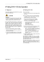
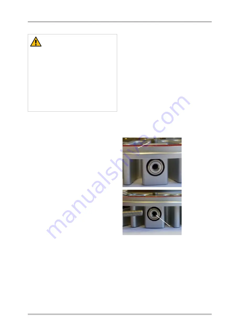
The pressure relief valve can be replaced with the
blind plug
by loosening the Allen screw on top of
DHS 1100 with a 2 mm Allen key (A). Insert a screw
(M4, not supplied by Anton Paar) into the embedded
valve to pull it out of the DHS 1100 (B).
Then insert the blind plug and tighten the Allen
screw.
1
Allen screw
2
Pressure relief valve
To
evacuate the sample stage
, proceed as fol-
lows:
1. Feed an appropriate vacuum hose through the
cabinet of the diffractometer and connect it to
the flange (DN16KF) on the connection device
of the DHS 1100 (refer to
ing the Gas Supply/Vacuum Equipment
).
2. Connect the vacuum hose to a suitable vacuum
pump, e.g. a rotary pump.
Between vacuum pump and DHS 1100 connec-
CAUTION
• Use a suitable pressure reducer/regulator
with a range from 0 to
5 bar and an accu-
racy of ± 0.1 bar to control the gas pressure
supplied to the DHS 1100.
• Make sure the pressure relief valve is not
blocked or closed with a blind plug.
• Avoid pressure bursts, because they can
destroy the dome.
• For flushing the instrument with gas, never
apply more than 1 bar pressure. This can
destroy the dome.
A
1
B
2
Содержание DHS 1100
Страница 2: ......
Страница 38: ...Appendix B Declaration of Conformity 38 C58IB004EN D Appendix B Declaration of Conformity ...


