background image

L-501 Models 


Anthony Lifgtates, Inc. 

800-482-0003  

www.anthonyliftgates.com

2.  

Safety Section

2.1  Safety is Your Responsibility

It is the responsibility of the installer/operator to 
understand and perform proper operating 
procedures.  Be aware of the inherent dangers in 

the use of this product and the tools used to install it.  
Read and understand all Danger, Warnings, Cautions, 
and Important Notices in this manual and on the liftgate 
or truck.

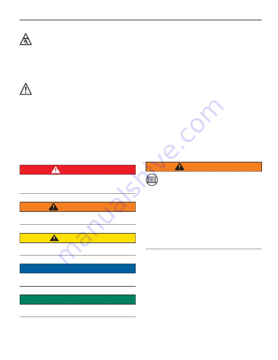
2.2  Safety Signal Words

This is the safety alert symbol. It is used to alert 
you to potential personal injury hazards. Obey all 
safety messages that follow this symbol to avoid 

possible injury or death.

This manual contains DANGERS, SAFETY 
INSTRUCTIONS, CAUTIONS, IMPORTANT NOTICES, 
and NOTES which must be followed to prevent the 
possibility of improper service, damage to the equipment, 
personal injury, or death. The following key words call the 
readers’ attention to potential hazards.

Hazards are identifi ed by the “Safety Alert Symbol” 
and followed by a signal word such as “DANGER”, 
“WARNING”, or “CAUTION”. 

DANGER

Indicates an imminently hazardous situation which, if 
not avoided, will result in death or serious injury.  This 
signal word is limited to the most extreme situations.

WARNING

Indicates a potentially hazardous situation which, if 
not avoided, could result in death or serious injury.

CAUTION

Indicates a potentially hazardous situation which, if 
not avoided, may result in minor or moderate injury. 

NOTICE

Indicates that equipment or property damage can result if 
instructions are not followed.

SAFETY
INSTRUCTIONS

Safety instructions (or equivalent) signs indicate 
specific safety-related instructions or procedures.

Note

:  Contains additional information important to a 

procedure.

2.3 Safety 

Rules

Accidents can often be avoided by being alert and 
recognizing potentially hazardous situations.  Any 
individuals installing, operating, repairing, or maintaining 
products manufactured by Anthony Liftgates should 
have the necessary training, skills, and tools required to 
perform these functions properly and safely.  The safety 
information in this manual serves as a basic guide in an 
attempt to prevent injury or death.

Anthony Liftgates cannot anticipate every possible 
circumstance that might involve a potential hazard.  The 
warnings in this manual and on the product itself are, 
therefore, not all-inclusive.  If tools, procedures, work 
methods, or operating techniques that are not specifi cally 
mentioned by Anthony Liftgates are used, you must 
satisfy yourself that they are safe for you and for others.  
Make sure the liftgate or truck it is mounted onto will 
not be damaged or made unsafe by any operation, 
lubrication, maintenance, or repair procedures that you 
choose.

DO NOT proceed, if any doubt arises about the correct or 
safe method of performing anything found in this or other 
Anthony Liftgates’ manuals.  Seek out expert assistance 
from a qualifi ed person before continuing.

WARNING

To avoid personal injury or death, carefully 
read and understand all instructions pertaining 
to the Anthony Liftgates product.  Do not 


attempt to install, operate, or maintain our product 
without fully understanding all of our instructions and 
safety recommendations.  Do not operate or work on 
a truck or liftgate unless you read and understand the 
instructions and warnings in the Installation and 
Operation manual.  If any doubt or question arises 
about the correct or safe method of performing 
anything found in this or other Anthony Liftgates’ 
manuals, contact your Anthony Liftgates’ dealer or 
call the Inside Sales and Service representatives at 
our main headquarters.  Proper care is your 
responsibility.

Содержание ALB-1500

Страница 1: ......

Страница 2: ......

Страница 3: ...ity Body 21 6 Optional Component Installation 23 6 1 Folding Step 23 6 2 Taillights 23 6 3 Cable Lug Installation 24 6 4 Attaching the Power Cable to Truck Frame 24 6 4 1 Clip or Tie Wrap Installation...

Страница 4: ...1 Limited Warranty 39 11 2 Warranty Policy and Procedure 39 12 Parts Section 40 12 1 Locking Mechanism Assembly Parts 40 12 2 Lifting Mechanism Assembly Parts 41 12 3 Linkage Assembly Parts 42 12 4 Pl...

Страница 5: ...familiarize yourself with its operation Important Operation Notes A platform restraining system may be needed to retain certain types of cargo on the liftgate platform such as a cart stop straps etc T...

Страница 6: ...the highest quality performance standards ALB liftgates are shipped completely assembled for fast clean and easy installation 1 5 Installation Recommendations Our liftgates should only be installed b...

Страница 7: ...ocedure 2 3 Safety Rules Accidents can often be avoided by being alert and recognizing potentially hazardous situations Any individuals installing operating repairing or maintaining products manufactu...

Страница 8: ...they remain clear of the cutting area To avoid eye injury always wear eye protection with the proper lens to protect your eyes Failure to prevent the truck from moving during the installation of the...

Страница 9: ...2 4 1 Personal Protection Important Information Read the manual Use proper tools Use two people when lifting heavy objects Weight rating Eye protection Breathing protection Set parking brake 2 4 2 Pro...

Страница 10: ...Foldover Section 10 Main Platform Section 11 Rear Platform Section 12 Cross Arm ALI 00111 13 12 2 1 11 9 7 8 5 4 3 6 10 Power Unit Nomenclature Item Description 1 Breather Tube 2 Hydraulic Cylinder at...

Страница 11: ...ns make sure all decals are attached to the liftgate and or truck and are legible at all times Safety decals provide a vital role in helping reduce injury and or death To ensure the greatest level of...

Страница 12: ...tem Part Number Description Qty 10 A 135087 Strap Washer 2 A 132085 1 2 13 x 1 Hex Head Cap Screw 10 A 150065 1 2 Flat Washer 10 A 150074 1 2 Lock Washer 10 ATU159 3 8 16 x 1 Carriage Bolt 5 2054 3 8...

Страница 13: ...easy to install the installation should be done with at least two people 1 Remove the banding securing the liftgate to the pallet 2 Remove the rear bumper and bumper brackets from the truck Remove the...

Страница 14: ...se the liftgate with a hoist or forklift 9 Position the liftgate so the mounting lip of the liftgate is resting on the truck bed and is as far forward as possible 10 Clamp the liftgate securely to the...

Страница 15: ...square holes in the liftgate mounting lip as a guide Mark the hole center punch and drill 12 Insert five 3 8 x 1 carriage bolts through the square holes and bolt the mounting lip of the liftgate to t...

Страница 16: ...torch in a well ventilated area and if in an enclosed area vent the fumes to the outside Breathing the smoke and fumes can cause serious injury Always follow all State and Federal health and safety la...

Страница 17: ...ecure the fuse assembly to a solid surface with wire ties or other suitable fasteners leaving a minimum of 6 of slack in the cable for changing the fuse 23 Route the supplied power cable with attached...

Страница 18: ...assis 25 Using the supplied ground cable ground the truck battery to the frame NOTICE The liftgate must be properly grounded A ground wire the same gauge or larger as the liftgate power cable must be...

Страница 19: ...ty all decals must be attached to the liftgate and be legible at all times Remember it is the users responsibility to maintain these decals For decal placement or a complete part number list and illus...

Страница 20: ...IS GROUNDED TO CHASSIS FRAME WITH 4 GAGE WIRE OR LARGER MAKE SURE POWER UNIT IS GROUNDED TO CHASSIS FRAME WITH 4 GAGE WIRE OR LARGER TO LIFTGATE SOLENOID Vehicle Starter Solenoid NOTE 1 Fuse should b...

Страница 21: ...h to withstand the forces the liftgate will put on it The body must be capable of withstanding a 1500 pound pull 20 inches above the truck floor Reinforce as needed A structural failure of the utility...

Страница 22: ...ual raising and lowering of the platform Adjust if necessary Once the H frame has been adjusted drill 3 8 holes through the brackets and the body walls Bolt the liftgate to the body walls using four 3...

Страница 23: ...p kit contains the step mounting bolts lock washers and flat washers 2 Bolt the step to the threaded mounting holes provided in the liftgate Make sure the textured surface of the step faces up 6 2 Tai...

Страница 24: ...g a cable crimping tool hydraulic or manual TYPE SGT TYPE SGT ALI 00104 NOTICE Proper wire connections are crucial to the life of the liftgate s power unit DO NOT crimp smash the cable lug with a hamm...

Страница 25: ...t remove power to the liftgate when the truck is left unattended A cut off switch or cut off solenoid will prevent the unauthorized use of the liftgate when the truck is not in use ALI 00116 LONG POWE...

Страница 26: ...cut off switch Cut off solenoid installed between battery and fuse assembly 1 Long cable leading to motor solenoid 2 Short end of power cable leading to fuse Follow the installation directions on the...

Страница 27: ...educe injuries and or death To ensure the greatest level of safety all decals must be in place and legible at all times Remember it is the users responsibility to maintain these decals For a complete...

Страница 28: ...Anthony Lifgtates Inc 28 L 501 Models www anthonyliftgates com 800 482 0003 2 A 135090 3 A 131015 4 Q 003013 5 A 150601...

Страница 29: ...L 501 Models 29 Anthony Lifgtates Inc 800 482 0003 www anthonyliftgates com 6 AR 18 76 ALI 00112 A 131066 05 2010 7 A 131036...

Страница 30: ...nit box Make sure it is properly secured Operate the liftgate through its entire operational cycle Up Down several times Make sure the liftgate operates evenly freely and smoothly throughout the entir...

Страница 31: ...level in the hydraulic reservoir monthly Change it if it is contaminated or dirty Visually inspect your liftgate frequently and keep it properly adjusted Repair any damage to the liftgate to prevent...

Страница 32: ...down the main deck platform ALI 00097 2 Fold open the flip over section of the platform ALI 00096 3 Press the Raise Lower toggle switch down to lower the platform ALI 00098 4 To close the gate press...

Страница 33: ...r replace if damaged 9 Check reservoir oil level a With the platform on the ground the oil level should be within 1 2 inch of the top of the reservoir b Fill as required with Dexron III or equivalent...

Страница 34: ...liftgate Connect the positive cable to the terminal on the motor start solenoid 3 If the motor operates the battery cable is defective and should be replaced 10 2 4 Checking Cylinder Piston Seals dri...

Страница 35: ...ny Lifgtates Inc 800 482 0003 www anthonyliftgates com 10 2 6 Checking Control Switch Fuse If the control switch is not operating the liftgate check the in line fuse located on the control cable insid...

Страница 36: ...d by weak batteries low voltage loose connections corrosion or a poor ground If the motor does not operate in freezing conditions make sure the motor housing does not contain water Liftgate will not l...

Страница 37: ...reservoir and make sure the return tube is below the oil level Hydraulic fluid leaking from cylinder Bad piston rod seals See Maintenance section for Checking Cylinder for Leakage 10 2 4 Checking Cyli...

Страница 38: ...Lifgtates Inc 38 L 501 Models www anthonyliftgates com 800 482 0003 10 4 Inspection Record Anthony LIftgates Inc ALB Liftgate Inspection Record Date of Inspection Notes observations maintenance perfor...

Страница 39: ...within 30 days of repair date will be denied NOTE ALL CLAIMS MUST BE COMPLETED ON THE ANTHONY LIFTGATES INC WARRANTY CLAIM FORM This form provides all the necessary information Upon approval of the cl...

Страница 40: ...Part No Description Qty 1 A 135020 H Frame 1 17 A 135008 Lock Arm 1 18 A 135011 Lock Link 1 19 A 132056 Teflon Washer 1 20 A 132057 1 2 Dia x 3 4 Long Shoulder Bolt 3 8 16 Thread 1 21 2064 3 8 16 Lock...

Страница 41: ...135018 R Cap Top Plate LH shown Cap Top Plate RH 1 26 A 135077 Platform Rotation Pin 1 27 A 135080 Cylinder Base Pin 1 28 A 135081 Cross Arm Pin 4 29 A 135082 Cylinder Rod End Pin 1 30 A 130240 Cylind...

Страница 42: ...RH Moving Post shown LH Moving Post 1 6 A 135039 Platform 1 7 A 135050 Platform Foldover 1 12 A 135060 Platform Long Link 1 13 A 135061 Platform Short Link 1 14 A 135062 Weldment Linkage Pivot Pin 1 1...

Страница 43: ...1 61 62 62 7 61 62 45 Item Part No Description Qty 6 A 135039 A 135126 Platform Platform Aluminum 1 7 A 135050 A 135140 Platform Foldover Platform Foldover Aluminum 1 8 A 135070 Rear Platform 1 45 A 1...

Страница 44: ...lic Components ALI 00113 2 8 3 7 1 4 5 6 Item Part No Description Qty 1 ATU125 Breather Line 60 2 2 A 130162 Barbed Fitting 2 3 A 130050 Pump Reservoir 1 4 A 130134 Hydraulic Hose 53 1 5 A 130154 Bran...

Страница 45: ...150095 Cable Ties 20 10 The Following Items are in Hardware Package A 135160 A 135087 Strap Washer 2 A 132085 1 2 13 x 1 Hex Head Cap Screw 10 A 150065 1 2 Flat Washer 10 A 150074 1 2 Lock Washer 10...

Страница 46: ...tion Qty Remarks 1 ATU 146 Stand Clear Do Not Ride on Lift 2 2 A 135090 Operating Instructions 1 3 A 131015 1500 lb Maximum Capacity 2 4 Q 003013 Urgent Warning Elevating Gate Instructions 1 5 A 15060...

Страница 47: ...L 501 Models 47 Anthony Lifgtates Inc 800 482 0003 www anthonyliftgates com 3 A 131015 4 Q 003013 5 A 150601 6 AR 18 76 ALI 00112 A 131066 05 2010 7 A 131036...

Страница 48: ...Anthony Lifgtates Inc 48 L 501 Models www anthonyliftgates com 800 482 0003 Notes...

Страница 49: ...L 501 Models 49 Anthony Lifgtates Inc 800 482 0003 www anthonyliftgates com Notes...

Страница 50: ...Anthony Lifgtates Inc 50 L 501 Models www anthonyliftgates com 800 482 0003 Notes...

Страница 51: ......

Страница 52: ......

Отзывы: