4.10 Checking Cylinder Piston Seals
4.10.1 Power Down Models
1. First, check the lowering valve. Make sure it is operating
correctly, and the valve is not sticking or dirty. Replace
the valve if necessary. Refer to “4.7 Checking Valve
Cartridge and Solenoid” on page 12.
2. Raise the platform approximately 12 inches off of the
floor.
3. Place a floor jack securely under the platform to support
its full weight. An overhead lifting device could also be
used.
4. Raise the floor jack until the platform begins to raise
slightly.
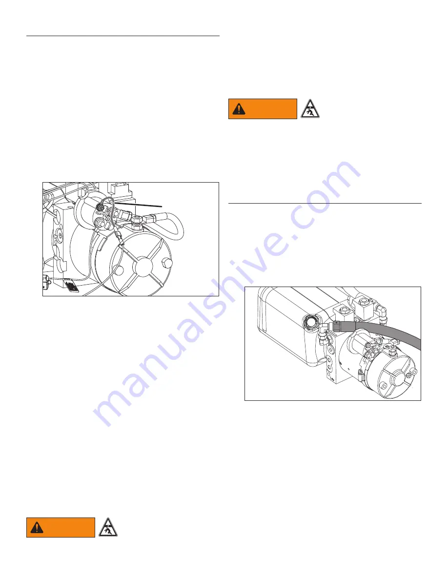
5. Disconnect the white wire from the motor start solenoid.
Place electricians tape around the end of the wire to
prevent it from making a ground connection.
White wire to
motor start
solenoid
759a
6. With the platform securely supported by the lifting
device, activate the control switch in the DOWN position
and hold the switch for 15 seconds. This will release
any pressure in the power down hose.
7. Now activate the control switch in the UP position and
hold it for 15 seconds. This will release any pressure in
the power up hose.
8. Repeat holding the control switch in the DOWN position
for 15 seconds and again in the UP position for 15
seconds. This should release any trapped pressure.
9. Carefully remove the flow control valve from the rod end
of the cylinder. Plug or cap the fitting.
10. Remove the hose from the cap end of the cylinder
and attach a temporary hose to catch any potential
leakage from the cylinder. Place the end of the hose in
a minimum one gallon container.
11. Lower the floor jack or lifting device.
12. Major seal damage will be apparent right away as
the platform would begin to slowly lower and fluid will
come out of the hose. Less extensive damage may
take longer to be seen. Allow the platform to sit for
several hours or overnight.
WARNING
Make sure nothing or no
one could accidentally go
under the platform while the
hoses are disconnected.
13. If the platform does not lower, the seals are not the
problem, most likely it is a faulty lowering valve.
14. Reconnect the white wire to the motor start termial.
Raise and lower the platform several times to remove
any trapped air.
4.10.2 Gravity Down Models
1. Completely raise the platform.
WARNING
Do not stand under the
platform.
2. Remove breather tube from the cap end of the cylinder
and attach a short piece of hose routed into a hand-
held container.
3. Activate the control switch in the UP position.
4. If oil is continuously pumped out of the hose, replace
the cylinder.
4.11 Checking System Pressure
For gravity down systems, there is only one relief valve
(power up). Power down models have two relief valve
settings; one for raising the platform (power up, upper
adjusting screw) and one for lowering the platform (power
down, lower adjusting screw).
To check the “power up” pressure setting:
1. Place the liftgate on the ground and remove the
pressure hose from the power up port of the pump.
725a
Power UP Model Pressure Hose Shown
2. Install a T-fitting (customer supplied) into the power up
port.
3. Connect a pressure gauge and reconnect the hydraulic
hose.
The pressure gauge must be rated above the maximum
pressure of the liftgate. For example, use a 4000
psi pressure gauge on a 3000 psi maximum capacity
liftgate.
4. Raise the liftgate and check the pressure on the gauge.


