


Antriebstechnik GmbH
Technical Documentation EC863 and ECE3AP-00-01
Page 9 of 18
(02/99) R0047GB.DOC
3.4.2
Control connections
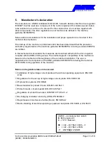
3.4.2.1 Auxiliary voltages
+10V (X2-9)
max. load 3 mA
+15V (X2-4)
max. load 50 mA
GND (X2-7)
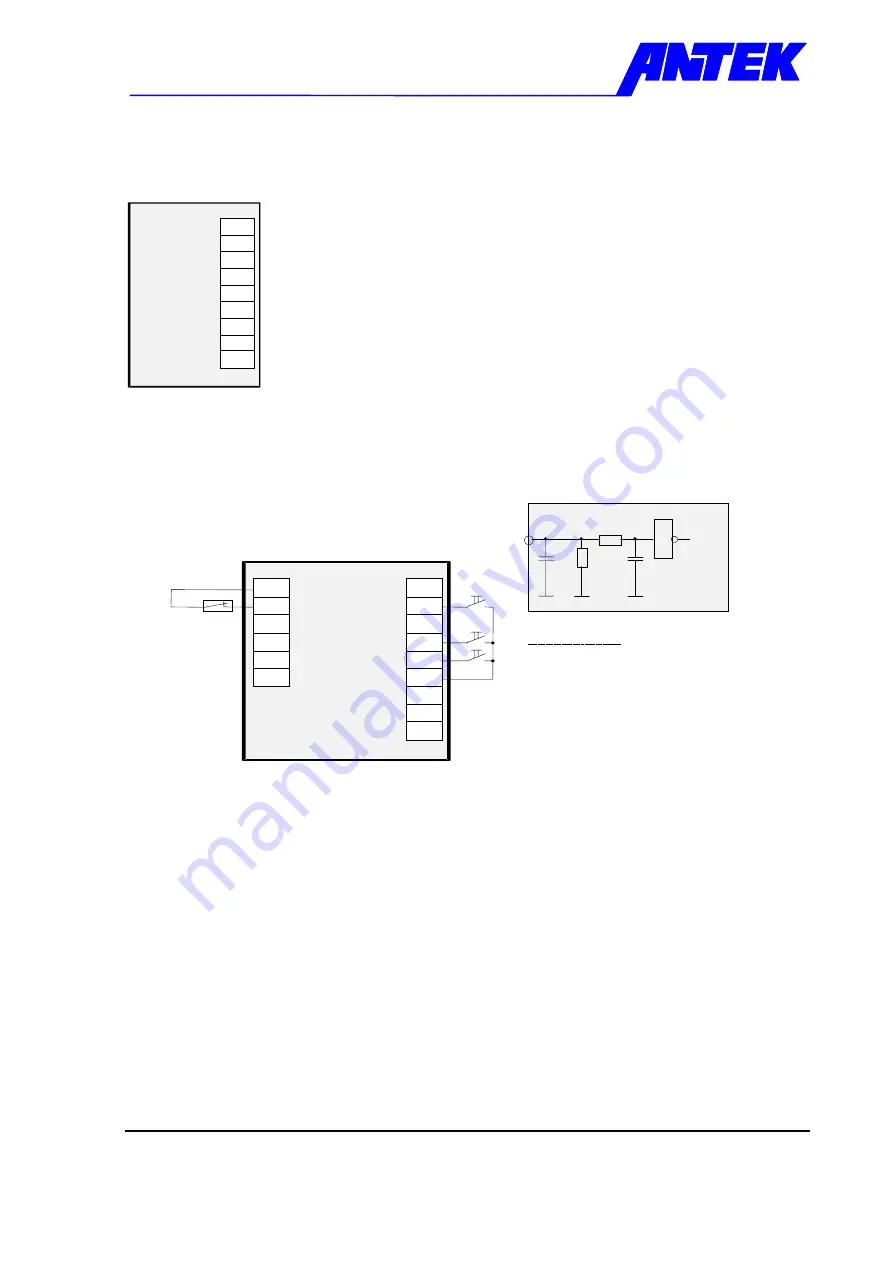
3.4.2.2 Connection of digital signals
n1 / n2 (X2-8)
The function fixed speeds can be selected with the plug bridge
STB3 „Set value source„ (see chapter 4.3).
HIGH = Selection fixed speed n2
LOW = Selection fixed speed n1
Left (X2-6)
HIGH = Selection of direction of rotation by connecting the
corresponding
Right (X2-5)
control voltage. If both direction of rotation inputs are selected, the
power amplifier remains cut-off..
LOW = power amplifier cut-off
M2 (X4-1)
Connection for the thermal circuit breaker (Break contact)
HIGH = Motor temperature in the work area, the LED „M2„ is lit up
to visualise the input.
LOW = Motor on excess temperature, stand-by signal contact is
tripped (see chapter 0).
Note:
If the motor does not have temperature monitoring via a thermal
circuit breaker, the connecting terminal X4-1 must be installed to
HIGH-Potential e.g. +15 V X4-2.
X2
Drive regulator
+15V
+10V
3
2
1
6
5
4
9
8
7
GND
X2
Drive regulator
n1 / n2
Left
+15V
1
0
n
k
1
0
k
µ
1
k
Digital-
input
1
100k
Circuit diagram
Pegeldefinition
HIGH = +12 ... +35 VDC
LOW = 0 ... +2 VDC or open
Reference potential GND
Input resistance
Take attention to equivalent reference
potential if you connect signal inputs and
outputs of control unit with periphere units.
3
2
1
6
5
4
9
8
7
Right
ϑ
X4
4
5
6
1
2
3
M2
+15V