background image

14

8.4 Test sequences

Use the item to run a special demo-test sequences without an external controller,which will show you some 

possibilities of using the fixture.

8.5 Stand-alone mode

Select this menu to set fixture behaviour in stand-alone mode without an external controller. 

Synchronous operation of multiple fixtures requires that they must be connected on a data link and one of them is 

set as a master ("MSt") and the rest as the slaves ("SLA").Only one fixture can be set  as the master.The slaves  

mimic the behavior of the master.Effect actions are triggered by an internal timer of the master fixture.

Important!:

Disconect the fixtures from the DMX controller before master/slave operating ,otherwise data col

-

lisions can occur and the fixtures  will not work properly!

MSt.

 ---

 Master.

Enter this menu if you want to set the the fixture as a master.Use [UP] and [DOWN] buttons to 

select desired program and press [ENTER] to confirm selection. 

SLA.

 ---

 Slave.

Enter this menu if you want to set the the fixture as a slave.

The master fixture starts simultaneous program start in the other slave fixtures.All fixtures are synchronized in 

every prog.steps.The fixtures run their programs repeatedly (e.g. if master runs its program "P05",all slaves will 

be executed program "P05" too).T

o ensure correct master/slave synchronization,switch on both master 

and slave at a time or first slave(s) and after that master.Running program has to be the same on all 

fixtures.

Note:

 If the master runs its editable program (EP1,EP2 or EP3),all slaves will execute their own editable pro

-

grams (EP1,EP2 or EP3) according the master,but both fade time (FA.t.) and standing time (S.tI.) for each step 

will  be taken from the master´s step (slaves´ times are eliminated in each step).

8.6 Special functions

Use this menu for special  services.

VEr.

 ---

 Software Version

.Select this function to read the number of the fixture software.

bAL.

 ---

 Balance

.Select this function to enable (On) or disable (OFF) the white balance which is set in "White 

colour balance" menu below.If this function is set OFF,ArcPower 72/K2 will use maximum value (255) of satu

-

ration for red, green and blue channel.

C.bA.

 ---

 White colour balance.

 Using this menu you can set white balance:

1.

 Browse through the menu by pressing the [UP] and [DOWN] buttons until the display shows "

C.bA

." menu.Press  

[ENTER] button and 

"rE.b."

 will appear on the display.

2

.Press [ENTER] button again and use [UP] and [DOWN] buttons to adjust the new maximum value required 

for the red channel.Confirm your choice by pressing [ENTER].Use the [UP] and [Down] buttons to select next 

colour.

3.

Repeat step 2 for green channel "

Gr.b.

" and for blue channel "

bL.b

".

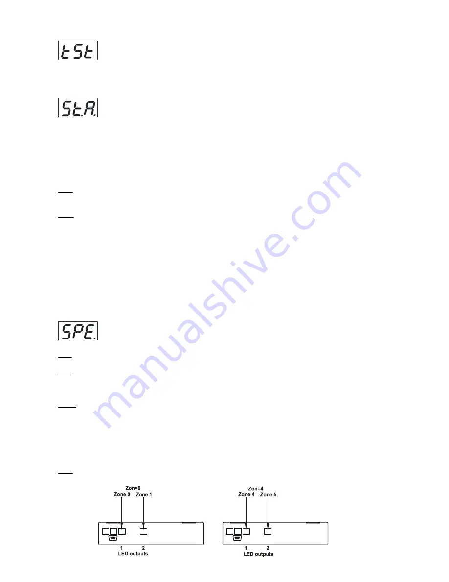
Zon.

 ---

 Zone selecting

.

 The option enables select desired number of the zone (from 0 to 8).

The number of the zone distinguishes individual zones of the ArcPower 7 which is controled via RS-3 

interface.

Содержание ArcPower 72/K2

Страница 1: ...version 1 7...

Страница 2: ...rating via DyNet protocol 9 6 ArcPower 72 K2 Control menu map 10 7 ArcPower 72 K2 DMX protocol 11 8 Control board 12 8 1 Addressing the ArcPower 72 K2 12 8 2 Program running 12 8 3 Manual mode 13 8 4...

Страница 3: ...fied employee Do not connect this unit to a dimmer pack Use a source of AC power that complies with local building and electrical rules AC power has to have both overload and short circuit protection...

Страница 4: ...re the end of the the supply cord and fit a suitable plug A 3 prong grounding type plug must be 1 Control board 2 Power Indicator 3 DMX Output 4 DMX Input 5 LED Zone outputs 6 RS 232 Output 7 Fuse Hol...

Страница 5: ...ientation and fixed by the 4 screws There are 4 mounting holes of diameter 5 mm in housing of the driver Ensure that instalation place is enough ventilated 4 3 Conection cables 1 The adapter cable RJ4...

Страница 6: ...g from the mains before installation 2 Connect the LED modules to the fixture Make sure that all modules include Luxeon K2 LED s 3 Connect the DMX controller to the fixture 4 Connect the fixture to th...

Страница 7: ...n be chained together At the last ArcPower 72 K2 the data link has to be terminated with a terminator A termination plug is simply a RJ45 connector with a 120 resistor between pins Data and Data Plug...

Страница 8: ...ll slaves are connected Up to 32 fixtures can be connected in master slave chain 4 Insert the termination plug with 120 Ohm into DMX input of the master fixture and into the DMX output of the last sla...

Страница 9: ...l level Byte 3 80 Channel Byte 4 ff Channel Offset Byte 5 00 Fade Rate Byte 6 FF fixed value Byte 7 1C Checksum Area 0 to 255 as set on the Arcpower to give a unique address for each Arcpower unit i e...

Страница 10: ...0 255 MAn rE1 0 255 FA t 0 255 Gr1 0 255 S tI 0 255 bL1 0 255 COP MAC 0 255 Str 0 255 diM 0 255 tSt St A MSt E P 1 P06 SLA SPE VEr bAL On OFF C bA rE b 0 200 Gr b 0 255 bL b 0 215 Zon Z 00 Z 08 d MP M...

Страница 11: ...135 136 143 144 151 152 159 160 167 168 175 176 183 184 191 192 199 200 207 208 215 216 223 224 231 232 239 240 247 248 255 Macro selection No function Macro 1 Macro 2 Macro 3 Macro 4 Macro 5 Macro 6...

Страница 12: ...the starting DMX address from which the ArcPower 72 K2 will respond to the DMX controller Setting the DMX start channel for DMX operating 1 Connect ArcPower 72 K2 to the mains 2 Browse through the men...

Страница 13: ...p select option COP and confirm it by pressing ENTER Both Fade time and Standing time use the same conversion table in order to convert DMX value to the time value DMX Time sec DMX Time min DMX Time m...

Страница 14: ...ion switch on both master and slave at a time or first slave s and after that master Running program has to be the same on all fixtures Note If the master runs its editable program EP1 EP2 or EP3 all...

Страница 15: ...rect values The menu items their name and order stated below match to a standard RGBW colour variant of LED modules connected to both LED inputs zones rE1 red LED s at zone 1 R rE2 red LED s at zone 2...

Страница 16: ...ture control panel SPE UPd yES From this option you cannot return back to the main menu If you do not want to continue in software update you have to switch off and on the fixture to leave this option...

Страница 17: ...main menu of the ArPower 72 K2 press ENTER use UP and DOWN buttons to select Zon The option enables to select desired number of the zone from 0 to 8 Press ENTER use UP and DOWN buttons to select zone...

Страница 18: ...means DMX value of the green colour 0 255 b means DMX value of the blue colour 0 255 means end of character sequence values of colours have to be separated by a comma Examples zone 0 234 126 165 zone...

Страница 19: ...e LED zone output and all its connected LED modules 20 metres at max load DMX channels Mode 1 6 channels Mode 2 8 channels Mode 3 11 channels Mode 4 4 channels Mode 5 4 channels Control and programmin...

Страница 20: ...45 DMX 5 pin No 13050731 11 Replacing the fuse 1 Before replacing the fuse unplug mains lead 2 Unscrew the fuse holder on the rear side of the ArcPower 72 K2 with a fitting screwdriver from the housin...

Отзывы: