OPTIMIZER HD
PAGE 11
Chapter 2 : STARTING
2-1. CONNECTIONS
c
Turn OFF all of your equipment before connecting.
d
Connect the AC power supply cord to the OPTIMIZER HD and to an AC power outlet.
e
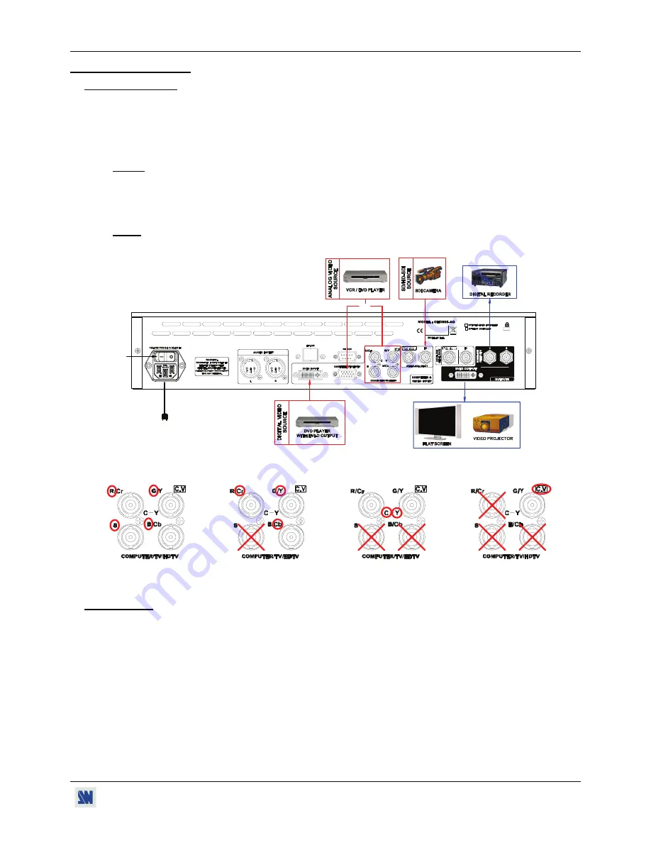
Connect your analog VIDEO sources to the TV/HDTV input connector (HD15 or BNC), your digital TV/HDTV
DVI source to the DVI connector and your SDI VIDEO source to the SD/HD-SDI IN connector (BNC).
NOTE:
Only one analog source can be connected at one time either on BNC or HD15 connector.
f
Connect the digital input of your display devices (flat screen, video projector, digital recorder...) to the
corresponding output connector (DVI-D or SDI of the OPTIMIZER HD).
g
Turn ON the OPTIMIZER HD (rear panel switch). Then turn ON your input source and then your display devices.
NOTE
: The GENLOCK IN & LOOP connectors are available on the OHD888-AG model only.
•
Example of connection (Model: OHD888-AG):
2
5
4
4
3
3
3
OR
•
Analog TV/HDTV source connection:
RGBS video
Component (Y, Cr, Cb) or
S.VIDEO (Y/C) source
Composite Video
source connection
RGsB source connection connection
source
connection
2-2. SETTINGS
c
We recommend resetting the OPTIMIZER HD to its default values, with the front panel display
menu
(
CONTROL
Default value
yes
) before proceeding.
d
Select the input type of the source connected to the input connectors with the front panel display
menu (
INPUT
DVI
or SDI or Analog type
) and activate the Auto detect function. The
Auto detect
function detects and selects
automatically the input type and format.
e
Select the Input status menu
(INPUT
Input status
) to verify the correct detection of the type and format of your input
source. If a wrong message is displayed, select manually the type of your input source (
INPUT
---
).
f
Select the output format and rate (
OUTPUT
Format
). For the DVI-D output, select the color space (RGB/YUV) and
the range (0>255 or 16>235).
g
Select the needed image adjustments (brightness, color…) available on the front panel and in the
IMAGE
menu.


