UG-061
Evaluation Board User Guide
Rev. 0 | Page 24 of
Metering Menu
Selecting the
Metering Functions
option under
MAIN MENU
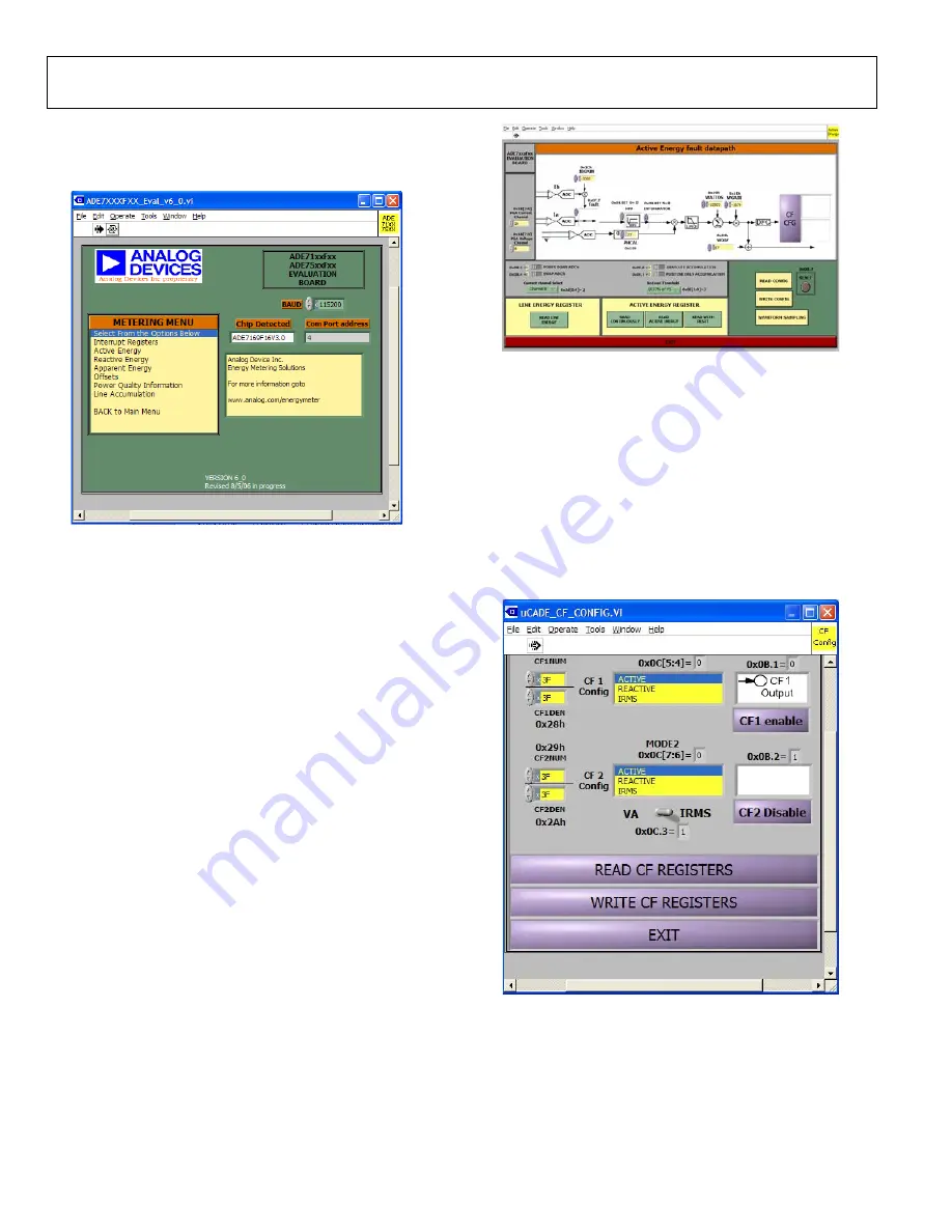
opens the secondary metering menu window shown in Figure 46.
08600-
048
Figure 46. Metering Menu
From this window, many of the energy metering functions can be
evaluated. Clicking each of the options shown under
METERING
MENU
opens a new window in front of the metering menu
window. Clicking the
EXIT
button in the new window brings
you back to the metering menu window. From
METERING
MENU
, you can return to the main menu window by clicking
the
BACK to Main Menu
option. Opening or closing new
windows does not cause the ADE71xx/ADE75xx registers to reset.
The
Interrupt Registers
window allows you to set up the inter-
rupt masks and view the status bits described in the ADE71xx/
ADE75xx data sheet. The
Power Quality Information
window
allows you to read the registers associated with the current and
voltage readings, along with monitoring the voltage channel
frequency, zero crossings, and line voltage sag events. The offset
calibration registers can be written to in the
Offsets
window. In
all windows, any changes made are not written to the part until
the corresponding
WRITE
button is clicked.
Active, Reactive, and Apparent Energy
The
Active Energy
,
Reactive Energy
,
and
Apparent Energy
options allow you to view the data path for each of these measure-
ments. The data path for the active energy data path is shown in
Figure 47.
08600-
049
Figure 47. Active Energy Window
Similar windows are available for the
Reactive Energy
and
Apparent Energy
data paths. From these windows, the data
paths can be configured and reset by writing to the necessary
registers. Changes made on the data path window are not
written to the part until the
WRITE CONFIG
button is clicked.
The energy data can also be read in either normal mode or line
cycle accumulation mode.
From the active energy, reactive energy, and apparent energy
windows, the calibration frequency output can be configured
using the
CF CFG
button. Clicking this button opens the
window shown in Figure 48.
08600-
050
Figure 48. Calibration Frequency
The two CF outputs can be configured and enabled from this
window. Once again, any changes made in the window are not
written to the part until the
WRITE CF REGISTERS
button is
clicked.
Содержание UG-061
Страница 28: ...UG 061 Evaluation Board User Guide Rev 0 Page 28 of PCB LAYOUT COMPONENT SIDE 08600 055 Figure 52 Layer 1...
Страница 29: ...Evaluation Board User Guide UG 061 Rev 0 Page 29 of PCB LAYOUT SOLDER SIDE 08600 056 Figure 53 Layer 2...
Страница 31: ...Evaluation Board User Guide UG 061 Rev 0 Page 31 of 3 NOTES...


