UG-061
Evaluation Board User Guide
Rev. 0 | Page 18 of
The project options required for each of the communication
methods are described in the following sections. These options
are also outlined in the
readme.txt
file included in the project
files. Note that the ADE7169Fxx and ADE5169Fxx template
projects default to using the USB-to-UART board settings for
downloading code to the target.
Project Options When Using the USB-to-UART Board
1.
In the
Analog Devices
category in the project options
window, select the
Download
tab.
2.
Select the
UART debug mode
check box.
3.
Select the
Ade device protocol
check box.
4.
The ADE71xx/ADE75xx/ADE51xx/ADE55xx incorporates
an internal downloaded verification; therefore, ensure that
the
verify download
button is cleared because the IAR
protocol is not supported.
Project Options When Using the Emulation Pod
In the
Analog Devices
category in the project options window,
select the
Download
tab. Clear the
UART debug mode
check box
and select the
Ade device protocol
box. The ADE71xx/ADE75xx/
ADE51xx/ADE55xx incorporates an internal downloaded
verification; therefore, ensure that the
verify download
box is
cleared because the IAR protocol is not supported.
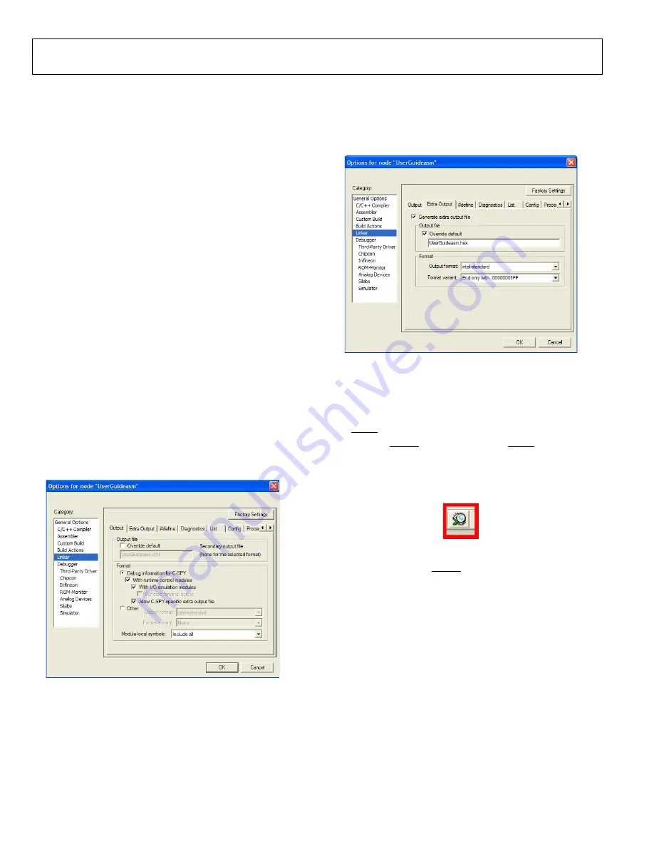
Creating a Hexadecimal File
The user can configure the project options so that IAR gene-
rates a hexadecimal file each time the project is built. This
hexadecimal file can then be downloaded to the part using the
serial downloader (see the Serial Downloader section). Select
the
Linker
category in the project options as shown in Figure 28.
08600-
030
Figure 28. Hexadecimal File Generation
1.
Under the
Output
tab, select the
Allow C-SPY-specific
extra output file
box.
2.
Under the
Extra Output
tab, in the
Output file
box,
type the name of the hexadecimal file that is going to be
generated complete with a .hex file type (see Figure 29).
08600-
031
Figure 29. Hexadecimal File Define
After the project has been built, the hexadecimal file can be
found in the project folder in the
Debug
>
Exe
subfolder.
Downloading User Firmware
Place the part in serial download mode by pressing and holding
the SDEN push-button, S2, while issuing a reset by pressing and
releasing the RESET push-button, S3. The SDEN
08600-
032
push-button
should then be released. When in serial download mode, click
the debug icon shown in Figure 30 located on the toolbar of the
IAR workbench.
Figure 30. IAR Debug Icon
When the download is complete, click the
Run
icon to start the
code. Alternatively, the RESET push-button, S3, can be pressed
to start the code.
Содержание UG-061
Страница 28: ...UG 061 Evaluation Board User Guide Rev 0 Page 28 of PCB LAYOUT COMPONENT SIDE 08600 055 Figure 52 Layer 1...
Страница 29: ...Evaluation Board User Guide UG 061 Rev 0 Page 29 of PCB LAYOUT SOLDER SIDE 08600 056 Figure 53 Layer 2...
Страница 31: ...Evaluation Board User Guide UG 061 Rev 0 Page 31 of 3 NOTES...


