UG-1673
Rev. 0 | Page 9 of 29
6.
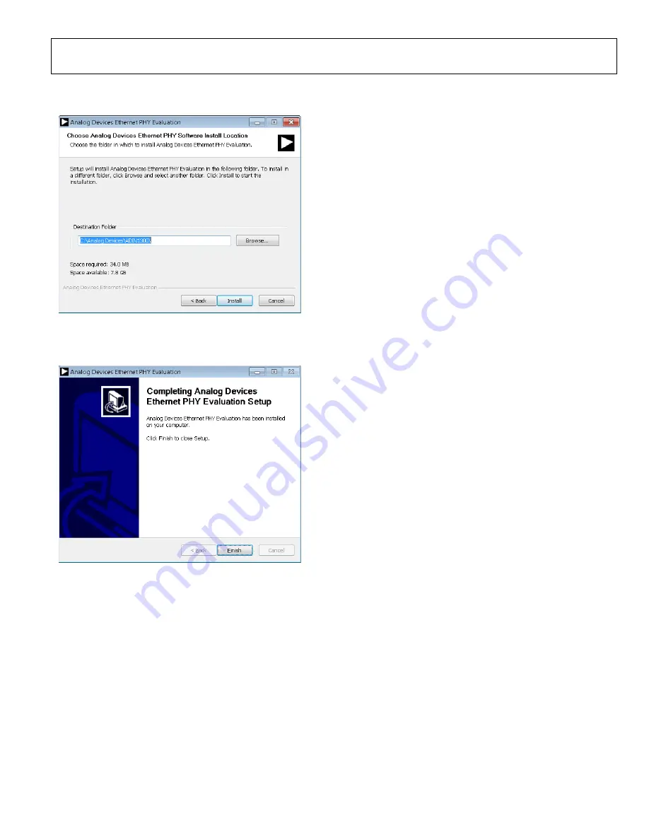
Select a location to install the Ethernet PHY software and
then click
Install
(see Figure 11).
22009-
0
1
1
Figure 11. Installation Location
7.
A window appears stating that the installation is complete.
Click
Finish
to continue (see Figure 12).
22009-
012
Figure 12. Installation Complete
8.
The Ethernet PHY software is automatically installed in the
Analog Devices
folder on the PC. The default folder name
is
ADIN1300
as the software GUI also supports the
. Access the Ethernet PHY software via
Windows® explorer at
C:\Analog Devices\ADIN1300
or
from the
Start
menu. When the software loads, it reads the
device MODEL_NUM to determine what device is
connected and configure the software GUI accordingly
(
INITIAL SETUP
To set up the EVAL-ADIN1200FMCZ and use it with the
Ethernet PHY software GUI, take the following steps:
1.
Connect a 5 V power supply to the EVAL-ADIN1200FMCZ
via the EXT_5V connector or the 5 V barrel connector.
2.
Connect the USB cable to the MDIO interface dongle.
3.
Connect the USB cable to the PC. When connecting the
EVAL-ADIN1200FMCZ to the PC for the first time, the
drivers are automatically installed. Wait until the driver
installation is complete before proceeding to the next step.
4.
microcontroller faces up (see
Figure 4) and connect the MDIO interface dongle to the
EVAL-ADIN1200FMCZ. The MDIO interface dongle is
not keyed.
5.
Launch the Ethernet PHY software from the
Analog
Devices
folder in the
Start
menu.


