background image

UG-154 

Evaluation Board User Guide 


Rev. 0 | Page 8 of 16 

INERTIAL SENSOR EVALUATION SYSTEM GRAPHICAL USER INTERFACE 

GETTING STARTED 


09113-

017


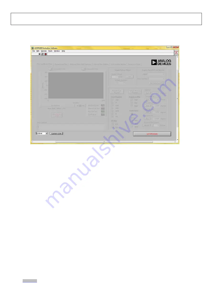
Figure 17. ADXRS800 Evaluation GUI Startup 

Before running the software evaluation GUI, it is a good idea to 
reset the ISEB by pressing the SW2 button described in the 
Installing the Latest ISEB Firmware section. This removes any 
errors that may be lingering due to an improper shutdown or 
disconnection from the PC. 
After completion of the software GUI installation routine, a 
shortcut to launch the executable is added to the 

Start

 menu. To 

launch the evaluation GUI, click 

Start/All Programs/ADXRS800 

Evaluation Software/ADXRS800 Eval

. A window similar to 

the one shown in Figure 17 is displayed. 
At this point, the functionality of the GUI is completely deac-
tivated. Before testing any devices, you must associate the 
software GUI with the previously installed hardware through 
the COM port. See 

PC Device Manager

 under the 

Ports (COM 

& LTP)

 submenu to determine which COM port is assigned to 

the Analog Devices inertial sensor evaluation system. Select this 
COM port from the drop-down menu, and click 

Confirm 

COM

 to begin using the GUI. 

After the COM port is confirmed, the full functionality of the 
software evaluation GUI is available for you to use. The 
following sections describe the purpose of each panel of the 
GUI. You can exit the GUI at any time by clicking 

QUIT 

PROGRAM

 located in the lower right of the startup window. 

Note that you should not press the reset button (SW2) while the 
GUI is running. This causes the ISEB and the software GUI to 
lose sync and also causes the evaluation system to no longer 
function properly. Additionally, if for any reason the ISEB board 
and the software evaluation GUI do not appear to be properly 
communicating, you should perform the following reset 
routine: 
1.


Close the software GUI by clicking the 

QUIT PROGRAM


or by selecting 

File/Exit

.


2.


When the software GUI is closed, reset the ISEB evaluation 
board by pressing the reset button (SW2).


3.


Restart the software GUI.


Downloaded from

Arrow.com.

Downloaded from

Arrow.com.

Downloaded from

Arrow.com.

Downloaded from

Arrow.com.

Downloaded from

Arrow.com.

Downloaded from

Arrow.com.

Downloaded from

Arrow.com.

Downloaded from

Arrow.com.

Содержание ADXRS800

Страница 1: ...onmental chamber for temperature or humidity testing Separating the boards mitigates corruption of data due to the temperature and humidity effects of other components The ISEB is a universal main boa...

Страница 2: ...ng the Latest ISEB Firmware 4 Hardware Configuration 7 Inertial Sensor Evaluation System Graphical User Interface 8 Getting Started 8 View and Record Data Panel 9 Temperature Test Panel 10 Noise and R...

Страница 3: ...need to select the drivers manually as follows 1 Connect the USB A to Mini B cable to the PC and then to the ISEB The satellite board does not need to be connected for this step New hardware is detec...

Страница 4: ...ed COM port of the ISEB hardware The Device Manager window should look like the window shown in Figure 6 09113 007 Figure 7 System Properties INSTALLING THE LATEST ISEB FIRMWARE The latest ISEB firmwa...

Страница 5: ...nd release SW2 c Release SW1 The download begins and is automatically verified by the downloader 2 If the downloading process fails which is indicated in the Monitor Status box see Figure 8 attempt th...

Страница 6: ...ent is displayed 3 Read the license agreement before accepting it then click Next The installer lists the required components to install on your PC see Figure 13 4 To start the installation click Next...

Страница 7: ...alternate high voltage supplies see the ADXRS800 data sheet and the Alternate External High Voltage Supply section of this guide ANALOG DEVICES ADXRS800 SATELLITE DEFAULT JUMPER POSITIONS CONNECTOR 0...

Страница 8: ...o the Analog Devices inertial sensor evaluation system Select this COM port from the drop down menu and click Confirm COM to begin using the GUI After the COM port is confirmed the full functionality...

Страница 9: ...indefinitely Secondary information that is transmitted along with the plotted signals is graphically represented This includes the fault register sequence bits status bits and sensor module bits This...

Страница 10: ...llow for an indefinite length for data recording Before recording the data on this panel you can adjust for null offset components Note that any offset correction made to the ADXRS800 is stored in the...

Страница 11: ...e free environment Any rotational rate input into the gyroscope can greatly degrade the validity of the resulting RAV plot Determining the rms noise of the ADXRS800 can be done on this same panel The...

Страница 12: ...Stability button You are then prompted to enter a file name for the data upon completion of the specified number of turn on cycles or upon clicking the Stop Data Record button While the test is runni...

Страница 13: ...avior of the ADXRS800 for incorporation into your system s algorithms For this test panel the first SPI message is typically received from the device within 20 ms after the ISEB supplies power to the...

Страница 14: ...llite board through 180 90 can also be used Because the satellite board is approximately square as each adjacent side is brought flush with the straight edge 90 of rotation will have been experienced...

Страница 15: ...bed in detail in the ADXRS800 data sheet The main requirement for the external high voltage supply is that 0 1 mA to 1mA of current be supplied to the device The nominal internal voltage is 22 5 V As...

Страница 16: ...of this Agreement Customer agrees to promptly return the Evaluation Board to ADI ADDITIONAL RESTRICTIONS Customer may not disassemble decompile or reverse engineer chips on the Evaluation Board Custo...

Отзывы: