

For full warranty information, refer to the AMX Instruction Manual(s) associated with your Product(s).
1/12
©2012 AMX. All rights reserved. AMX and the AMX logo are registered trademarks of AMX.
AMX reserves the right to alter specifications without notice at any time.
3000 RESEARCH DRIVE, RICHARDSON, TX 75082 • 800.222.0193 • fax 469.624.7153 • technical support 800.932.6993 • www.amx.com
93-2105-90
REV: D
Installing Into an Equipment Rack
Use the optional AC-RK Accessory Rack Kit (
FG515
) to mount the Controller into a standard 19"
equipment rack.
1.
Discharge the static electricity from your body by touching a grounded object.
2.
Align the front of the NI-900 through any of the three rectangular openings on the AC-RK.
3.
Use the included mounting screws to secure the unit’s faceplate to the AC-RK.
4.
Thread the cables through the opening in the equipment rack. Allow for enough slack in the
cables to accommodate for movement during the installation process.
5.
Reconnect all cables to their appropriate source/terminal locations. Verify that the terminal
end of the power cable is not connected to the a power supply before plugging in the 2-pin
power connector.
6.
Align the ends of the AC-RK with the screw openings along the sides of the equipment rack.
7.
Secure the AC-RK to the rack by using the four #10-32 screws (80-0186) and four #10
washers (80-0342) supplied in the kit.
8.
Apply power to the unit to complete the installation process.
Connections and Wiring
Preparing Captive Wires
You will need a wire stripper and flat-blade screwdriver to prepare and connect the captive wires.
Note
: Never pre-tin wires for compression-type connections.
1.
Strip 0.25 inch (6.35 mm) of insulation off all wires.
2.
Insert each wire into the appropriate opening on the connector (according to the wiring dia-
grams and connector types described in this section).
3.
Tighten the screws to secure the wire in the connector. Do not tighten the screws excessively
doing so may strip the threads and damage the connector.
Wiring a Power Connection
To use the 2-pin 3.5 mm mini-Phoenix connector with a 12 VDC-compliant power supply, the
incoming PWR and GND cables from the external source must be connected to their corresponding
locations on connector (FIG. 2).
1.
Insert the PWR and GND wires on the terminal end of the 2-pin 3.5 mm mini-Phoenix cable.
Match the wiring locations of the +/- on both the power supply and the terminal
connector.
2.
Tighten the clamp to secure the two wires.
3.
Verify the connection of the 2-pin 3.5 mm mini-Phoenix to the external 12 VDC-compliant
power supply.
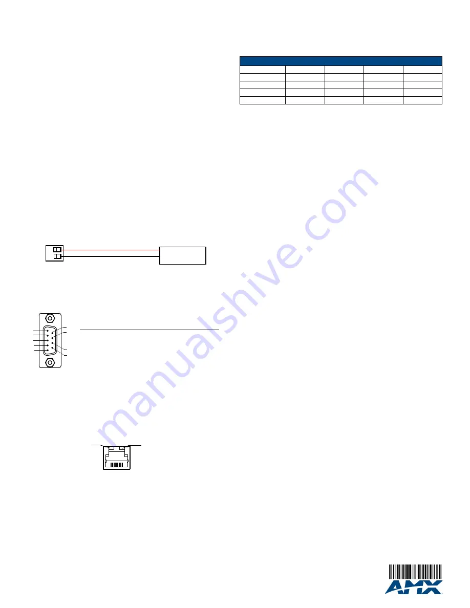
RS-232/422/485 Connector Information
FIG. 3 shows the pinout and wiring specification information for the rear RS-232/RS-422/RS-485
(DB9) Device Port. This port support most standard RS-232 communication protocols for data
transmission (the NI-900 uses only Port 1).
WARNING:
When wiring the 422/485 connections, do
NOT
use pre-made 9-wire cable or connect
the wire in the cable to any connection that will not be used by the DB9 serial port. Only use wiring
that connects the needed pins.
Ethernet 10/100 Base-T Connector
A standard CAT5 Ethernet cable provides 10/100 network connectivity between the Integrated
Controller and the network (FIG. 4).
Note
: On NetLinx Masters (such as those aboard the NI-900), from within the Telnet or Terminal
applications; you can send the
SET ETHERNET MODE
command to assign the speed of your
Ethernet connection.
Sample NI-900 command:
SET ETHERNET MODE AUTO
The NI-900 only allows you to set the Ethernet mode to AUTO negotiate the Ethernet connection
speed. Using any of the other connection modes (10 Half/Full or 100 Half/Full) results in an error
message.
Program Port Baud Rate Settings
The Configuration DIP switch is located on the front panel. Use this DIP switch to set the baud rate
for the Program Port, according to the settings shown in the following table. Make sure the baud rate
you set matches the baud rate on your PC's NetLinx COM Settings before programming the unit.
By default, the baud rate is set to 38,400 (bps)
.
Note:
DIP switch 1 activates/deactivates the Program Run Disable Mode. DIP Switches 2,3, and 4
must remain OFF at all times.
Setting the Configuration (Program Port) DIP Switch
1.
Disconnect the power supply from the rear 2-pin PWR (green) connector.
2.
Set DIP switch positions according to the information listed in the previous Baud Rate
Settings table.
3.
Reapply power to the unit.
Preparing the NI-900 for Serial Communication
1.
Launch NetLinx Studio 2.x (default location is
Start
>
Programs
>
AMX Control Disc
>
NetLinx Studio 2
>
NetLinx Studio 2
).
2.
Select
Settings
>
Master Communication Settings
, from the Main menu, to open the
Master Communication Settings
dialog box.
3.
Click the
Communications Settings
button to open the
Communications Settings
dialog.
4.
Click the
NetLinx Master
radio button (from the Platform Selection section) to indicate you
are working with a NetLinx Master.
5.
Click the
Serial
radio button (from the Transport Connection Option section) to indicate you
are connecting to the Master via a COM port.
6.
Click the
Edit Settings
button (on the
Communications Settings
dialog) to open the
Serial
Settings
dialog and set the COM port parameters (used to communicate to the NetLinx
Master).
7.
Click the
OK
button three times to return to the main application.
8.
Right-click the entry in the
Online Tree
tab and select
Refresh System.
9.
Assign a System Value by using
Diagnostics
>
Device Addressing
from the Main menu.
10.
Enable the
Change System selection
by clicking on it and then enter the current and new
System values.
11.
Click the
Change Device/System Number
button and when finished click
Done
.
12.
Select
Tools
>
Reboot the Master Controller
to access the
Reboot the Master
dialog, then
click
Reboot
to restart the Master and incorporate any changes.
13.
Once the dialog replies with "
Reboot of system complete
", click
Done
and then click the
OnLine Tree
tab in the Workspace window to view the devices on the System.
The default
System value is one
.
14.
Right-click on the
Empty Device Tree/System
entry and select
Refresh System
to re-
populate the list.
Configuring the NI-900 for Ethernet Communication
Before continuing, complete the COM port steps above.
1.
Connect an Ethernet cable to the unit’s rear Ethernet connector.
2.
Select
Diagnostics
>
Network Address
from the Main menu and enter the System, Device
(0 for a Master
), and Host Name information.
3.
To configure the Address:
•
Use a DHCP Address by selecting the
Use DHCP
radio button, then click the
GET IP
button
(
to obtain a DHCP Address from the DHCP Server
), click the
SET IP Information
button (
to
retain the new address
), and then finish the process by clicking the
Reboot Master
>
OK
buttons.
•
Use a Static IP Address by selecting the
Specify IP Address
radio button, enter the IP
parameters into the available fields, then click the
SET IP Information
button (
to retain the
pre-reserved IP Address to the Master
), and then click the
Reboot Master
>
OK
buttons to
finish the process.
4.
Repeat steps 1 - 5 from the previous section but rather than selecting the
Serial
option,
choose
TCP/IP
and edit the settings to match the IP Address you are using (whether Static or
IP).
5.
Click on the
Authentication Required
radio box (
if the Master is secure
d) and press the
User Name and Password
button to enter a valid username and password being used by
the secured Master.
6.
Click the
OK
button three times to return to the main application.
Additional Documentation
Additional Documentation for the NI-900 is available at www.amx.com:
•
Refer to the
NI-700/900 Hardware Reference Guide
for additional details on Installation,
Upgrading, and Wiring the NI-900.
•
Refer to the
NI Series NetLinx Integrated Controllers WebConsole & Programming Guide
for
detailed configuration instructions.
FIG. 2
2-pin mini-Phoenix connector wiring diagram (direct power)
FIG. 3
RS-232/422/485 DB9 (male) connector pinouts
FIG. 4
Layout of Ethernet LEDs
PWR +
GND -
To the Integrated Controller
Power Supply
5
4
3
2
1
9
8
7
6
Male
DB9 Serial Port
pinouts (male connector)
Pin 2: RX signal
Pin 3: TX signal
Pin 5: GND
Pin 7: RTS
Pin 8: CTS
RS-232
Pin 1: RX -
Pin 4: TX +
Pin 5: GND
Pin 6: RX +
Pin 9: TX -
RS-422
Pin 1: A (strap to 9)
Pin 4: B (strap to 6)
Pin 5: GND
Pin 6: B (strap to 4)
Pin 9: A (strap to 1)
RS-485
10/100
ETHERNET
SPD
L/A
SPD
- Speed LED lights (yellow) when
and turns Off when the speed
is 10 Mbps.
the connection speed is 100 Mbps
L/A
- Link/Activity LED lights
(green) when the Ethernet
cables are connected and
terminated correctly.
Baud Rate Settings
Baud Rate
Position 5
Position 6
Position 7
Position 8
9600 bps
OFF
ON
OFF
ON
38,400 bps (default)
OFF
ON
ON
ON
57,600 bps
ON
OFF
OFF
OFF
115,200 bps
ON
ON
ON
ON


