background image

Wiring and Device Connections

30

Enova DVX-3150HD/3155HD All-in-One Presentation Switcher Operation/Reference Guide

PROGRAM Port

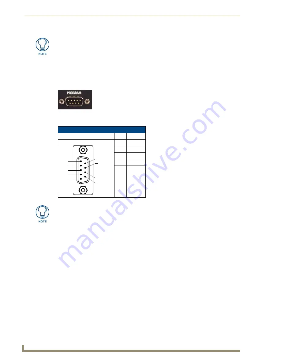
The PROGRAM port is a DB-9 male RS-232 port that connects the DVX to a communication port on a PC, 
and is intended primarily to be used to configure system settings (FIG. 41). 

The following table shows the rear panel Program Port connector (male), pinouts, and signals.   

Think of the PRD Mode (On) equating to a PC’s SAFE Mode setting. This mode 
allows you to continue powering a unit, update the firmware, and download a new 
program while circumventing any problems with a currently downloaded program. 
Power must be cycled to the unit after activating or deactivating this mode on the 
Configuration Port DIP switch #1.

FIG. 41  

PROGRAM port

Program Port, Pinouts, and Signals

Program Port Connector

Pin

Signal

2

RX

3

TX

5

GND

7

RTS

8

CTS

5
4
3
2
1

9
8

7
6

The PROGRAM port is not recommended for firmware updates or large file transfers. 
Any large data-intensive operations are better handled via LAN.

Содержание Enova DVX-3150HD

Страница 1: ...ble SUPPORTED VIDEO RESOLUTIONS Up to 1920 x 1200 60Hz 3D and Surround Sound Support HDCP Compliant DIMENSIONS HWD 5 3 16 x 17 x 14 WEIGHT 18 2 lb Includes 2 CC NIRC IR Emitter w 3 5mm Phoenix 1 CC DVIM VGAF DVI to VGA Adapter 2 Front Rack Mounting Brackets Installation Guide View more DVX 3150HD SP product information Your selected PDF begins on the next page ...

Страница 2: ...ation Switchers Enova DVX 3150HD 3155HD 10x4 All in One Presentation Switcher DVX 3150HD SP DVX 3150HD T DVX 3155HD SP DVX 3155HD T Latest Release 09 13 2012 Enova DVX 3150HD 3155HD 10x4 All In One Presentation Switcher Operation Reference Guide ...

Страница 3: ...rked on the outside of each box The RMA is valid for a 30 day period After the 30 day period the RMA will be cancelled Any shipments received not consistent with the RMA or after the RMA is cancelled will be refused AMX is not responsible for products returned without a valid RMA number AMX is not liable for any damages caused by its products or for the failure of its products to perform This incl...

Страница 4: ...nplug this apparatus during lightning storms or when unused for long periods of time 14 Refer all servicing to qualified personnel Servicing is required when the apparatus has been damaged in any way such as power supply cord or plug is damaged liquid has been spilled or objects have fallen into the apparatus the apparatus has been exposed to rain or moisture does not operate normally or has been ...

Страница 5: ...Important Safety Instructions ii Enova DVX 3150HD 3155HD All in One Presentation Switcher Operation Reference Guide ...

Страница 6: ...LEDs 11 LCD Display 11 SWITCH Pushbutton 12 TAKE Pushbutton 12 VIDEO MENU Pushbutton 12 AUDIO MENU Pushbutton 13 Navigation Pushbuttons 13 STATUS Pushbutton 14 EXIT Pushbutton 14 VIDEO AUDIO MUTE Pushbuttons 14 Rear Panel Audio Inputs and Outputs 15 AUDIO INPUTS 1 4 15 HDMI INPUTS 5 10 15 AUDIO INPUTS 11 14 15 MIC INPUTS 1 2 17 AMP OUT 18 AUDIO OUTPUTS 19 S PDIF OUTPUT 19 Rear Panel Video Inputs a...

Страница 7: ...BNC Male Cable 37 DVI to 5 BNC Cable Pinout Information 37 DVI A Male to Triple RCA Male Cable 38 DVI to Triple RCA Cable Pinout Information 38 DVI A Male to S Video Male Cable 40 DVI to S Video Cable Pinout Information 40 DVI A Male to HD15 VGA Male Adapter 41 DVI to VGA Cable Pinout Information 41 HDMI Male to DVI D Male Cable 43 HDMI to DVI D Cable Pinout Information 43 Audio Video Configuratio...

Страница 8: ...ding Audio on an HDMI Output 64 Mixing Microphones onto Analog and HDMI Outputs 65 System Settings 66 NetLinx Firmware Upgrades 67 Overview 67 Before You Start 67 Sending Firmware KIT Files to the DVX 67 Additional Documentation 70 Programming 71 NetLinx Channels and Levels 72 NetLinx Channels 72 Standby Mode 73 NetLinx Levels 74 SEND_COMMANDS 75 AUDIO SEND_COMMANDs 76 AI input O output 76 AUDIN_C...

Страница 9: ..._CF 81 AUDMIC_EQ_CF 81 AUDMIC_EQ_FT 81 AUDMIC_EQ_FT 82 AUDMIC_EQ_GAIN 82 AUDMIC_EQ_GAIN 82 AUDMIC_EQ_Q 82 AUDMIC_EQ_Q 82 AUDMIC_GAIN 83 AUDMIC_GAIN 83 AUDMIC_GATING 83 AUDMIC_GATING 83 AUDMIC_GATING_ATTACK 83 AUDMIC_GATING_ATTACK 83 AUDMIC_GATING_DEPTH 84 AUDMIC_GATING_HOLD 84 AUDMIC_GATING_RELEASE 84 AUDMIC_GATING_RELEASE 84 AUDMIC_GATING_THRESH 84 AUDMIC_LIMITER 84 AUDMIC_LIMITER 85 AUDMIC_LIMIT...

Страница 10: ...OUT_EQ_FT 89 AUDOUT_EQ_FT 90 AUDOUT_EQ_GAIN 90 AUDOUT_EQ_GAIN 90 AUDOUT_EQ_MODE 90 AUDOUT_EQ_MODE 90 AUDOUT_EQ_Q 91 AUDOUT_EQ_Q 91 AUDOUT_MAXVOL 91 AUDOUT_MAXVOL 91 AUDOUT_MINVOL 91 AUDOUT_MINVOL 92 AUDOUT_MUTE 92 AUDOUT_MUTE 92 AUDOUT_STEREO 92 AUDOUT_STEREO 92 AUDOUT_TESTTONE 92 AUDOUT_TESTTONE 93 AUDOUT_VOLUME 93 AUDOUT_VOLUME 93 GAIN 93 GAIN 93 HDMIOUT_AUDIO 93 HDMIOUT_AUDIO 94 HDMIOUT_EQ 94 H...

Страница 11: ... 98 VIDIN_COLOR 98 VIDIN_CONTRAST 98 VIDIN_CONTRAST 98 VIDIN_EDID 98 VIDIN_EDID 98 VIDIN_EDID_AUTO 99 VIDIN_EDID_AUTO 99 VIDIN_FORMAT 99 VIDIN_FORMAT 99 VIDIN_HDCP 99 VIDIN_HDCP 100 VIDIN_HSHIFT 100 VIDIN_HSHIFT 100 VIDIN_HUE 100 VIDIN_HUE 101 VIDIN_NAME 101 VIDIN_NAME 101 VIDIN_PHASE 101 VIDIN_PHASE 101 VIDIN_PREF_EDID 102 VIDIN_PREF_EDID 102 VIDIN_RES_AUTO 102 VIDIN_RES_AUTO 102 VIDIN_RES_REF 10...

Страница 12: ..._OSD 106 VIDOUT_OSD_COLOR 107 VIDOUT_OSD_COLOR 107 VIDOUT_OSD_POS 107 VIDOUT_OSD_POS 107 VIDOUT_RES 107 VIDOUT_RES_AUTO 107 VIDOUT_RES_AUTO 107 VIDOUT_RES_REF 108 VIDOUT_RES_REF 108 VIDOUT_SCALE 108 VIDOUT_SCALE 108 VIDOUT_TESTPAT 108 VIDOUT_TESTPAT 109 VIDOUT_VSHIFT 109 VIDOUT_VSHIFT 109 VIDOUT_VSIZE 109 VIDOUT_VSIZE 109 Front Panel SEND_COMMANDs 110 FP_LOCKOUT 110 FP_LOCKOUT 110 FP_LOCKTYPE 110 ...

Страница 13: ...lutions 113 Available Pixel Display and Refresh Rates 113 DVI HDMI and VGA Supported Input Resolutions 113 Composite and S Video Supported Input Resolutions 115 Component Video Supported Input Resolutions 115 Appendix B Output Resolutions 117 Available Pixel Display and Refresh Rates 117 DVI and HDMI Supported Output Resolutions 117 ...

Страница 14: ...nments and conference rooms including those supporting audio and video conferencing It also fits well in classrooms and auditoriums that need multiple displays or video previewing Audio Processing The DVX 3150HD and DVX 3155HD feature built in audio mixing and amplification that outputs two channels at 25 Watts each into 8 ohms after passing through a mixer and an integrated equalizer to accommoda...

Страница 15: ...control data on Ports 9 16 I O yellow 8 LEDs indicate that I O channels 1 8 are active on Port 17 LCD display Liquid crystal display 2 lines with 20 characters per line indicates current volume level and displays the Video Audio and Status menus See the LCD Display section on page 11 for details SWITCH pushbutton Press to access the Switch menu on the LCD display Use the menu to choose to switch a...

Страница 16: ...ly Two 2 position captive wire connectors provide 70V or 100V mono amplified audio output T models only See the AMP OUT section on page 18 for more information AUDIO OUTPUTS 3 3 5mm 5 pin captive wire connector provides for balanced or unbalanced mono or stereo line level audio output See the AUDIO OUTPUTS section on page 19 for more information S PDIF OUTPUT 1 Coaxial RCA connector provides digit...

Страница 17: ... of the AxLink port The AxLink port can be used to supply power to downstream AxLink compatible devices as long as the maximum current draw is less than 1 Amp Note The AxLink port provides only limited power to connected AxLink devices It is recommended to use an alternate power source when connecting AxLink devices to the DVX Note When using the DVX with the NXA PDU 1508 8 power distribution unit...

Страница 18: ... Screw 8 32 x 375 PFH Undercut BLACK 80 0145 2 CC NIRC IR Emitter with 3 5mm Phoenix Connector FG10 000 11 1 CC DVIM VGAF DVI to HD 15 Female Adapter FG10 2170 13 Optional Accessories CC DVI 5BNCM DVI to 5 BNC adapter cable FG10 2170 08 CC DVI RCA3M DVI to 3 Male RCA adapter cable for component and composite connections FG10 2170 09 CC DVI SVID DVI to S Video adapter cable FG10 2170 10 CC DVIM VGA...

Страница 19: ...ckets should be attached to the DVX 3 Install the DVX in the mounting rack by using the mounting screws to affix the unit to the rack 4 Connect any applicable wires to the DVX Refer to the Wiring and Device Connections section on page 9 for wiring diagrams and pinout descriptions Connect the unit only to a properly rated supply circuit The left and right mounting brackets are not identical Please ...

Страница 20: ...entilation requirements of all the items of equipment installed within the rack The maximum operating ambient temperature is 40 C 104 F When installing equipment into a rack distribute the units evenly Otherwise hazardous conditions may be created by an uneven weight distribution Reliable earthing grounding of rack mounted equipment should be maintained The DVX should not be installed in enclosed ...

Страница 21: ...Overview 8 Enova DVX 3150HD 3155HD All in One Presentation Switcher Operation Reference Guide ...

Страница 22: ...nd rear panel of the DVX Wiring specifications are also provided when applicable FIG 3 displays the front panel of the DVX 3150HD and DVX 3155HD FIG 3 DVX 3150HD SP front panel VIDEO MUTE AUDIO MUTE EXIT pushbutton STATUS pushbutton VIDEO MENU AUDIO MENU TAKE pushbutton SWITCH pushbutton Navigational pushbuttons LINK ACT LED STATUS LED OUTPUT LED INPUT LED RS232 422 485 LEDs Relay LEDs IR Serial L...

Страница 23: ... that two DXLink inputs appear in place of two of the HDMI inputs FIG 5 displays the rear panel of the DVX 3150HD T FIG 4 DVX 3150HD SP rear panel FIG 5 DVX 3155HD SP rear panel MULTI FORMAT VIDEO INPUTS AUDIO HDMI INPUTS INPUTS AMP OUTPUT AUX AUDIO INPUTS OUTPUTS Power RS232 422 485 ports RELAYS port 8 I O Port 17 IR SERIAL Ports 9 16 AUDIO OUPUTS AxLink Port LED Config DIP switch ID pushbutton P...

Страница 24: ...icates current status of any adjustments made to settings within these menus FIG 6 Front Panel LEDs Front Panel LEDs Label Color Description LINK ACT green Blinks when receiving LAN data packets STATUS green Blinks to indicate that the system is programmed and communicating properly INPUT yellow Blinks to indicate that the Controller is receiving data OUTPUT red Blinks to indicate that the Control...

Страница 25: ... FIG 10 to access the video options displayed on the LCD display There are two video menus VIDEO OUTPUT and VIDEO INPUT and both are accessible by using this button Multiple presses cycle through the various VIDEO menus The Video menu enables you to see and adjust most parameters of the video input and output signals Use the UP and DOWN navigational buttons to traverse the various configuration pa...

Страница 26: ...n Pushbuttons The four directional navigation buttons Left Right Up Down enable you to navigate through and adjust the configurable parameters shown on the LCD display The UP and DOWN navigation buttons are used to move between configurable parameters within a menu Pressing UP takes you to the previous configuration parameter Pressing DOWN takes you to the next configuration parameter These button...

Страница 27: ...ved when you advance to another option or exit the menu The menu exits automatically after no user interaction on the front panel for 30 seconds See the Status Menu section on page 52 for a listing of all available options and instructions on how to change the settings EXIT Pushbutton Press the EXIT pushbutton FIG 14 to exit any menu on the LCD display VIDEO AUDIO MUTE Pushbuttons Press the VIDEO ...

Страница 28: ...tion on page 22 If you are using a DVX 3155HD you have two DXLink input ports which support embedded audio in place of HDMI input ports 9 10 See the DXLink INPUTS 9 10 section on page 23 for more information AUDIO INPUTS 11 14 The four AUDIO INPUTS connectors are 3 5 mm 5 position captive wire terminals that can be wired for either balanced differential or unbalanced single ended stereo audio FIG ...

Страница 29: ...ame system FIG 19 provides details for wiring from an audio input to a an unbalanced source device that has RCA connectors Positive and ground wires connect to the source You also can use a CC 3 5ST5 RCA2F 2 RCA Female to 5 Pin Phoenix Cable FG10 003 20 for this type of connection FIG 18 Stereo 5 terminal wiring FIG 19 RCA Stereo audio source wiring Balanced wiring Unbalanced wiring DVX source dev...

Страница 30: ...UT connectors FIG 20 allow up to two mono microphones to be connected to the DVX Each microphone input supports balanced and unbalanced audio Each input supports up to 48V of phantom power FIG 21 illustrates wiring connections between the DVX and a mono RCA output and an XLR output FIG 20 MIC INPUTS FIG 21 RCA mono and XLR output wiring DVX RCA output DVX XLR output ...

Страница 31: ...o 2 position captive wire connectors for T models provide 70V or 100V mono amplified audio output Connect a speaker to either the 70V or 100V terminal but not both simultaneously On SP models connect speakers to the AMP OUT output as displayed in FIG 23 On T models connect a speaker to either the 70V or 100V terminals as displayed in FIG 24 FIG 22 AMP OUT CLASS 2 WIRING Output FIG 23 Connecting sp...

Страница 32: ...unbalanced single ended connections FIG 26 illustrates options for wiring between output connectors and the destinations S PDIF OUTPUT The S PDIF OUTPUT provides digital S PDIF audio output that can mirror any of the 4 analog audio outputs or 4 HDMI outputs FIG 25 Audio outputs FIG 26 Stereo 5 terminal wiring Balanced wiring Unbalanced wiring DVX destination device Do not connect the negative term...

Страница 33: ...out configuration of the MULTI FORMAT VIDEO INPUT connectors FIG 28 MULTI FORMAT VIDEO INPUTS DVI I connectors The MULTI FORMAT VIDEO INPUT connectors on the DVX are DVI I integrated digital analog connectors These connectors support both DVI A analog and DVI D digital inputs MULTI FORMAT VIDEO INPUT Connectors Pinouts and Signals Pin Signal Pin Signal Pin Signal 1 TMDS Data2 9 TMDS Data1 17 TMDS ...

Страница 34: ... page 38 DVI A Male to S Video Male Cable section on page 40 DVI A Male to HD15 VGA Male Adapter section on page 41 HDMI Male to DVI D Male Cable section on page 43 The following table displays the supported video settings for each type of input connection The DVX and the adapter cables listed above utilize industry standard pinouts The only adapter cable that is unique to AMX is the CC DVI SVID D...

Страница 35: ... with 3D and Deep Color and HDCP The following table describes the pinout configuration of the HDMI INPUTS connectors FIG 30 displays the pin locations for the HDMI INPUTS FIG 29 HDMI INPUTS connectors HDMI INPUT Connectors Pinouts and Signals Pin Signal Pin Signal 1 TMDS Data 2 11 TMDS Clock Shield 2 TMDS Data 2 Shield 12 TMDS Clock 3 TMDS Data 2 13 CEC 4 TMDS Data 1 14 Reserved HEC Data 5 TMDS D...

Страница 36: ...onal control over twisted pair cable to DXLink devices or boards including digitally transcoded analog video signals Both inputs support HDCP These connectors are only available on the DVX 3155HD See the Important Cable Recommendations section on page 25 for information about cable requirements for these ports DVI Input Adapter Cables Name Description Length FG HDMI Interface Cable HDMI Male to HD...

Страница 37: ...ategory Cable to DXLink Receivers See the Important Cable Recommendations section below for information about cable requirements FIG 32 displays the HDMI and DXLink audio video output ports FIG 33 displays male and female RJ 45 connectors You can connect the DVX to the DXLink receivers via Category cabling On Video outputs 1 and 3 if you are using both DXLink and HDMI outputs it is recommended tha...

Страница 38: ...e used with DXLink equipment However cable run topology and environmental influences can affect the overall successful distance capabilities of these runs For successful deployments up to 100 meters without consideration to outside variables AMX recommends the use of shielded category cable STP or Cat6A or better versions of unshielded or shielded twisted pair UTP STP for DXLink runs For more deta...

Страница 39: ... connectors FIG 35 RS 232 422 485 Device Port connectors FIG 36 RS 232 422 485 DB9 male connector pinouts RS 232 422 485 Port Wiring Specifications Pin Signal Function RS 232 RS 422 RS 485 1 RX Receive data X X strap to pin 9 2 RXD Receive data X 3 TXD Transmit data X 4 TX Transmit data X X strap to pin 6 5 GND Signal ground X X X 6 RX Receive data X X strap to pin 4 7 RTS Request to send X 8 CTS ...

Страница 40: ...ix female connector provides relay termination I O PORT 17 The I O port FIG 38 responds to switch closures and voltage level high low changes or can be used for logic level outputs A contact closure between the GND and an I O port is detected as a Push When used for voltage inputs the I O port detects a low signal 0 1 5 VDC as a Push and a high signal 3 5 5 VDC as a Release this I O port uses 5V l...

Страница 41: ...ce Supports high frequency carriers of up to 1 142 MHz 8 IR Serial data signals can be generated simultaneously The IR Serial connector wiring specifications are listed in the following table FIG 39 IR SERIAL connectors IR Serial Connector Wiring Specifications per Port IR connections Port Signal Function 1 9 GND Signal 1 Signal GND IR Serial data 2 10 GND Signal 2 Signal GND IR Serial data 3 11 G...

Страница 42: ...s causing inadvertent communication and or control problems If necessary place the on board Master in PRD mode and cycle power then use the NetLinx Studio v 3 x program to resolve the communication and or control problems with the resident NetLinx program After doing so download the corrected program reset the configuration DIP switch to normal mode recycle power and try again To set the CONFIG DI...

Страница 43: ...RD Mode On equating to a PC s SAFE Mode setting This mode allows you to continue powering a unit update the firmware and download a new program while circumventing any problems with a currently downloaded program Power must be cycled to the unit after activating or deactivating this mode on the Configuration Port DIP switch 1 FIG 41 PROGRAM port Program Port Pinouts and Signals Program Port Connec...

Страница 44: ... which allows you to use either straight through or crossover Ethernet cables The LAN port automatically negotiates the connection speed 10 Mbps or 100 Mbps and whether to use half duplex or full duplex mode This communication is reflected via the front ICSP LED FIG 44 provides the pinouts and signals for the LAN connector and cable FIG 45 describes the blink activity for the LAN connector and cab...

Страница 45: ...commended that you power external AxLink devices from an independent power supply Refer to the following table for the wiring length information used with the DVX FIG 47 provides wiring requirements for the AxLink connector FIG 46 AxLink Port and LED The AxLink port provides only limited power to connected AxLink devices It is recommended to use an alternate power source when connecting AxLink dev...

Страница 46: ... DVX FIG 48 4 pin mini Phoenix connector wiring diagram using external power source Top view Top view To the Controller s AxLink PWR connector To the external AxLink device Local 12 VDC power supply coming from an external power supply When you connect an external power supply do not connect the wire from the PWR terminal coming from the external device to the PWR terminal on the Phoenix connector...

Страница 47: ...Wiring and Device Connections 34 Enova DVX 3150HD 3155HD All in One Presentation Switcher Operation Reference Guide ...

Страница 48: ...t and HDMI to the DVI Input connectors the following optional adapter cables are required FIG 50 DVI Inputs DVI Input Adapter Cables Name Description Length FG CC DVI 5BNCM DVI to 5 BNC Male Note Used for VGA Component or Composite inputs When used for composite inputs connect the green plug on the adapter cable to the composite video output jack on the source device 6 1 828m FG10 2170 08 CC DVI R...

Страница 49: ...TMDS DATA 1 N TMDS DATA 1 N 9 28AWG twisted pair 1 10 TMDS DATA 1 P TMDS DATA 1 P 10 28AWG twisted pair 1 11 TMDS SHIELD 1 3 TMDS SHIELD 1 3 11 28AWG twisted pair 1 drain 12 TMDS DATA 3 N TMDS DATA 3 N 12 Pin not populated in DVI D connector 13 TMDS DATA 3 P TMDS DATA 3 P 13 Pin not populated in DVI D connector 14 5VDC 5VDC 14 28AWG 15 GROUND GROUND 15 28AWG 16 HOT PLUG DETECT HOT PLUG DETECT 16 2...

Страница 50: ...7 DDC DATA Pin populated in DVI A connector but not connected for this cable 8 ANALOG VERTICAL SYNC VSync Signal Black BNC center pin 9 TMDS DATA 1 N Pin not populated in DVI A connector 10 TMDS DATA 1 P Pin not populated in DVI A connector 11 TMDS SHIELD 1 3 Pin not populated in DVI A connector 12 TMDS DATA 3 N Pin not populated in DVI A connector 13 TMDS DATA 3 P Pin not populated in DVI A conne...

Страница 51: ...pe corresponds to the CC DVI RCA3M DVI to Component Composite cable FG10 2170 09 available from AMX DVI to Triple RCA Cable Pinout Information DVI A Connector Pin Signal Name Signal Name RCA connector pin Notes 1 TMDS DATA 2 N Pin populated in DVI A connector but not connected for this cable 2 TMDS DATA 2 P Pin populated in DVI A connector but not connected for this cable 3 TMDS SHIELD 2 4 Pin not...

Страница 52: ...ELD 0 5 Pin not populated in DVI A connector 20 TMDS DATA 5 N Pin not populated in DVI A connector 21 TMDS DATA 5 P Pin not populated in DVI A connector 22 TMDS CLOCK SHIELD Pin not populated in DVI A connector 23 TMDS CLOCK P Pin populated in DVI A connector but not connected for this cable 24 TMDS CLOCK N Pin populated in DVI A connector but not connected for this cable C1 C1 ANALOG RED Componen...

Страница 53: ... for this cable 8 ANALOG VERTICAL SYNC Pin populated in DVI A connector but not connected for this cable 9 TMDS DATA 1 N Pin not populated in DVI A connector 10 TMDS DATA 1 P Pin not populated in DVI A connector 11 TMDS SHIELD 1 3 Pin not populated in DVI A connector 12 TMDS DATA 3 N Pin not populated in DVI A connector 13 TMDS DATA 3 P Pin not populated in DVI A connector 14 5VDC Pin populated in...

Страница 54: ...ND Y C Returns shields 1 2 BACKSHELL SHIELD Pin populated in DVI A connector but not connected for this cable This cable type corresponds to the CC DVIM VGAF DVI to VGA adapter FG10 2170 13 available from AMX DVI to VGA Cable Pinout Information DVI A Connector Pin Signal Name Signal Name HD15 VGA Pin Notes 1 TMDS DATA 2 N Pin populated in DVI A connector but not connected for this cable 2 TMDS DAT...

Страница 55: ...or 21 TMDS DATA 5 P Pin not populated in DVI A connector 22 TMDS CLOCK SHIELD Pin not populated in DVI A connector 23 TMDS CLOCK P Pin populated in DVI A connector but not connected for this cable 24 TMDS CLOCK N Pin populated in DVI A connector but not connected for this cable C1 C1 ANALOG RED RED Coax Signal 1 Red mini coax signal C2 C2 ANALOG GREEN GREEN Coax Signal 2 Green mini coax signal C3 ...

Страница 56: ...ation HDMI Connector Pin Signal Name Wire DVI D Pin Notes 1 TMDS Data 2 A 2 2 TMDS Data Shield B 3 3 TMDS Data 2 A 1 4 TMDS Data 1 A 10 5 TMDS Data Shield B 11 6 TMDS Data 1 A 9 7 TMDS Data 0 A 18 8 TMDS Data 0 Shield B 19 9 TMDS Data 0 A 17 10 TMDS Clock A 23 11 TMDS Clock Shield B 22 12 TMDS Clock A 24 13 CEC N C N C 14 Reserved N C N C 15 SCL C 6 16 SDA C 7 17 DDC CEC Ground D 14 18 5V Power 5V...

Страница 57: ...Cable Details and Pinout Information 44 Enova DVX 3150HD 3155HD All in One Presentation Switcher Operation Reference Guide ...

Страница 58: ... front panel FIG 51 shows the LCD display The LCD backlight on the display turns off after 35 seconds of inactivity Press the TAKE pushbutton to implement an audio video switch while you are in the Switch menu on the LCD display If you are in any menu other than Switch press the button to cycle through audio and or video inputs Use the Navigational buttons to traverse the available configuration p...

Страница 59: ...Hatch If you have uploaded a logo to display on the output you can also select the logo from this option Logo images must be 24 bit color bitmap files at least 36x36 pixels in size Blank Screen Use the left and right navigational buttons to select the color of the blank screen on the output You can choose from Black or Blue The default setting is Black If you have uploaded a logo to display on the...

Страница 60: ...ult setting is Component For HDMI inputs you can choose from HDMI or DVI Auto Resolution Use the left and right navigational buttons to toggle whether you want the video input resolution to be set automatically The default setting is ON Resolution Use the left and right navigational buttons to manually select the correct resolution and refresh rate of the selected output For a complete list of out...

Страница 61: ... the appropriate aspect ratio Selecting a Video Test Pattern Selecting a test pattern for your input source can help determine if the displays are connected correctly Perform these steps the select a test pattern 1 Press the VIDEO MENU button on the front panel of the DVX to open the Video Output menu 2 Press the left and right navigation buttons to select the output on which to display the test p...

Страница 62: ...u can choose from Out1 Out2 Out3 Out4 Pass thru and Off HDMI EQ Use the left and right navigational buttons to toggle whether the equalizer settings for the selected analog output should be applied to the HDMI output You can choose from On or Off The default value is Off SPDIF SRC Use the left and right navigational buttons to indicate the audio stream to output through the S PDIF output You can c...

Страница 63: ...ings for the microphone Mic Input Select Use the left and right navigational buttons to manually select which microphone input you want to use When in Dual Mode you can choose from 1 or 2 Enable Use the left and right navigational buttons to toggle whether the selected microphone is active You can choose from Off or On The default setting is Off Preamp Gain Use the left and right navigational butt...

Страница 64: ...h Switch Menu Switch Level Use the SWITCH button to indicate whether you want to switch the Video Audio or Both The subsequent options in this menu depend on your choice with this option see below Select A V Input Use the SWITCH button to cycle through the available inputs This option is only available if you select Both on the Switch Level option Select A V Output Use the SWITCH button to cycle t...

Страница 65: ...ddress Displays the IP address of the network IP Subnet Mask Displays the subnet mask of the network IP Gateway Displays the gateway address of the network IP DNS Addr Displays the IP or DNS address of the device Master FW Version Displays the version number of the firmware the Master is using Device FW Version Displays the version number of the firmware the device is using DSP FW Version Displays...

Страница 66: ...DVX resides on 1 Open a web browser and type the IP Address of the target DVX in the Address Bar 2 Press Enter to access WebConsole for that DVX The initial view is the WebControl page FIG 53 FIG 53 Master Configuration Manager WebControl Page initial view Select this option to show hide the Online Device Tree showing all devices currently connected to this Master System Device info System read on...

Страница 67: ...s the top of the main page FIG 54 WebControl This is the option that is pre selected when the WebConsole is accessed Use the options in the Manage WebControl Connections page to manage G4WebControl connections Security Click to access the System Security page The options in this page allow you to configure various aspects of NetLinx System and Security on the Master System Click to access the Syst...

Страница 68: ...tcher in the location bar of the web browser If you do not know your switcher s IP address see the Locating the IP Address of the DVX section on page 56 The Main WebControl page opens FIG 55 3 Use the Device options menu at the top of the screen to select the DEVICE DVX 315xHD x Switch Device Substitute the model number of your unit for x The Enova DVX Setup page opens FIG 57 If a web browser or F...

Страница 69: ...locate the All In One Presentation Switcher s IP address Note the IP address for future reference General Options The WebConsole Configuration page contains settings that are accessible from each tab FIG 56 indicates the universally accessible options available on the web pages The following table lists the general options for the WebConsole Configuration page You can use the Status Menu to verify...

Страница 70: ...devices on the same port as the DVX 2 Blank Color Logo Use the drop down menu to select the color of the blank screen on the output If you have uploaded a logo to display on the output you can also select the logo from this menu 3 OSD This area allows you to activate the on screen display When enabled the input name and resolution displays in a small box in a corner of the screen whenever you sele...

Страница 71: ...ailable for storing the three image files The amount of free space remaining appears on the screen See the Uploading an Image File section on page 58 for more information Note Large images can cause a slowdown in performance Though images up to 1920x1200 are supported AMX recommends using an image size no greater than 640x480 8 Scaling Click Auto to have the unit automatically set the video resolu...

Страница 72: ...ify each input The name you enter here appears in the on screen display OSD if enabled The lettering changes color depending on whether video is detected on the selected input Green indicates a signal is detected grey indicates a signal is detected but cannot be identified and red indicates no signal is detected You can enter up to 63 characters for a single name Space characters are valid however...

Страница 73: ...f you select one of the internal EDID files All Full or Wide In this mode you can select the specific preferred resolution to present to the connected source The Auto EDID Update check box and the update EDID button are only available if you select to mirror the EDID from a connected display Select the Auto EDID Update check box if you want the EDID sent to the source to update anytime the EDID re...

Страница 74: ... to hear audio from the selected source You can choose from Off 60Hz 250Hz 400Hz 1kHz 3kHz 5kHz 10kHz Pink Noise and White Noise 8 Equalizer The equalizer is a 10 band parametric equalizer enabling you to set any of the 10 default frequencies 31Hz 62Hz 125Hz 250Hz 500Hz 1000Hz 2000Hz 4000Hz 8000Hz 16000Hz to any value from 20Hz to 20KHz Each band is set individually by selecting the band from the ...

Страница 75: ...electing any option other than Off enables you to adjust settings for Attack Release Ratio and Threshold Attack Sets the duration in milliseconds of the attack phase while compressing You can set a value between 1 and 2000 Release Sets the duration in milliseconds of the release phase while compressing You can set a value between 1 and 5000 Ratio Sets the ratio while compressing You can set a valu...

Страница 76: ...ny value between 20Hz and 20KHz Gain Use the up and down arrow buttons or direct text entry to adjust the gain attention level of the audio input You can set the gain from 12 to 12dB in 1dB increments The default setting is 0 Q Q factor adjusts the vector graph from wider to narrower smoothing between inflection points on the equalizer band The default setting is 1 4 The range is from 0 1 to 20 0 ...

Страница 77: ... Follow these same steps when receiving surround audio from a DXLink input and or sending audio to DXLink outputs Connect all DXLink transmitters receivers to the DVX connect sources and sinks to DXLink transmitters receivers and select the appropriate DXLink input output on the DVX in the steps above Embedding Audio on an HDMI Output Follow these steps to configure an HDMI DXLink or S PDIF output...

Страница 78: ...B 4 If the connected microphone requires phantom power check the Phantom Power check box for that microphone input see item 6 in the Audio In Microphone section on page 62 for more information 5 In the same section turn on the connected microphone by checking the Enable check box for that microphone input 6 On the Audio Output tab select each analog audio output see item 1 in the Audio Out section...

Страница 79: ... any web browser AMX has tested except Microsoft Internet Explorer when HTTP Security is enabled on the DVX Master 3 Microphone Mode Click the checkboxes to activate or deactivate the microphones connected to Mic Inputs 1 and 2 when in Dual Mode or the L R Microphone when in Single Stereo Mode 4 Front Panel Lockout Mode Click the check box to activate a lockout of some or all of the buttons on the...

Страница 80: ...t DVX By default the Device Number assigned to the DVX is 0 zero The Master device number is always 0 and cannot be changed The Device Number can be viewed on the DVX Configuration Manager Device Configuration page 6 Launch NetLinx Studio and open the Online Device Tree Sending Firmware KIT Files to the DVX Use the Firmware Transfers options in the Tools menu to update the firmware in the DVX NetL...

Страница 81: ...evice to open the Send To NetLinx Device dialog FIG 62 2 Click the Browse button to navigate to the target directory in the Browse For Folder dialog FIG 63 The selected directory path is displayed in the Send To NetLinx Device dialog Location text box FIG 62 Send To NetLinx Device dialog NetLinx Studio FIG 63 Browse For Folder dialog NetLinx Studio Browse for folder containing the KIT file ...

Страница 82: ...n changed 5 Review the File Connection Address and Target Device information before you send 6 Click the Send button You can watch the progress of the transfer in the Send to NetLinx Device dialog NetLinx Studio transfers the files to the DVX and then tells it to reboot After it reboots the DVX actually goes through the upgrade process During the upgrade process the Status LED blinks and the DVX s...

Страница 83: ...Linx Studio refer to the NetLinx Studio online help and Operation Reference Guide available at www amx com If for any reason your Kit file transfer should fail continue to retry the transfer until you are successful DO NOT reboot the DVX or change connections until the transfer is complete Failure to complete this operation successfully may require a factory repair of the DVX ...

Страница 84: ...all commands compatible with the NI 3101 SIG Some DVX 2100HD commands operate under different names on the DVX 3150HD The functionality of these commands are identical to their original counterparts SEND_COMMAND Changes Original Command New Command AUDIO_MUTE AUDOUT_MUTE AUDIO_MUTE AUDOUT_MUTE INPUTEQ AUDMIC_EQ INPUTEQ AUDMIC_EQ PHANTOM_PWR AUDMIC_PHANTOM_PWR PHANTOM_PWR AUDMIC_PHANTOM_PWR OSD VID...

Страница 85: ... 42 1 4 Switches audio input 2 to the video output specified in the DPS 43 1 4 Switches audio input 3 to the video output specified in the DPS 44 1 4 Switches audio input 4 to the video output specified in the DPS 45 1 4 Switches audio input 5 to the video output specified in the DPS 46 1 4 Switches audio input 6 to the video output specified in the DPS 47 1 4 Switches audio input 7 to the video o...

Страница 86: ...implemented and any changes will be noticed after the DVX exits Standby Mode All audio and video signals are restored in less than 10 seconds after exiting Standby Mode The DVX exits Standby Mode on any power cycle or reboot NetLinx Channels Cont Channel Ports Description 143 1 14 Gain Mute 144 1 14 Gain Cycle 148 1 10 Video In Brightness Ramp Up 149 1 10 Video In Brightness Ramp Down 150 1 10 Vid...

Страница 87: ...4 12 12 Audio EQ Band 1 32 1 4 12 12 Audio EQ Band 2 33 1 4 12 12 Audio EQ Band 3 34 1 4 12 12 Audio EQ Band 4 35 1 4 12 12 Audio EQ Band 5 36 1 4 12 12 Audio EQ Band 6 37 1 4 12 12 Audio EQ Band 7 38 1 4 12 12 Audio EQ Band 8 39 1 4 12 12 Audio EQ Band 9 40 1 4 12 12 Audio EQ Band 10 41 1 4 100 0 Audio Program Source Mixing Level 42 1 4 100 0 Audio Line Mic 1 Mixing Level 43 1 4 100 0 Audio Line ...

Страница 88: ...ur Video output ports 05002 1 0 05002 2 0 05002 3 0 and 05002 4 0 Input and Output functional distinctions are disambiguated from the overlapped port numbers by combining them with the command name The following table lists the port functionality mapping for the audio video ports on the DVX Port Functionality Mapping Port Number Description Address 1 Audio Video Input 1 05002 1 0 2 Audio Video Inp...

Страница 89: ...UDIN_COMPRESSION Sets the compression for the audio port Sets the setting of compression for the audio port addressed by the D P S Syntax SEND_COMMAND DEV AUDIN_COMPRESSION setting Variable setting off low medium high custom Example SEND_COMMAND AUDIO_INPUT_1 AUDIN_COMPRESSION high Sets the compression setting of the audio input port 1 based on D P S to high AUDIN_COMPRESSION _ATTACK Requests the ...

Страница 90: ...ession release for the audio port Requests the compression s release Syntax SEND_COMMAND DEV AUDIN_COMPRESSION_RELEASE Example SEND_COMMAND AUDIO_1 AUDIN_COMPRESSION_RELEASE Returns a COMMAND string of the form AUDIN_COMPRESSION_RELEASE release AUDIN_COMPRESSION _RELEASE Sets the compression release for the audio port Sets the duration of the release phase while compressing for the audio port addr...

Страница 91: ...rt Sets the gain of the audio port addressed by the D P S to gain Syntax SEND_COMMAND DEV AUDIN_GAIN gain Variable gain 24 to 24 in dB Example SEND_COMMAND AUDIO_INPUT_1 AUDIN_GAIN 12 Sets the gain of the audio input port 1 based on D P S to 12 dB AUDIN_STEREO Requests the stereo setting of the input port Requests to see if the audio port addressed by the D P S has the stereo setting enabled or di...

Страница 92: ...of the attack phase while compressing for the microphone port addressed by the D P S Syntax SEND_COMMAND DEV AUDMIC_COMPRESSION_ATTACK attack Variable attack 1 to 2000 Example SEND_COMMAND MICROPHONE_1 AUDMIC_COMPRESSION_ATTACK 200 Sets the compression attack for the microphone port 1 based on the D P S to 200 AUDMIC_COMPRESSION _RATIO Sets the compression ratio for the microphone port Sets the ra...

Страница 93: ...200 AUDMIC_DUCK_HOLD Sets the ducking hold for the microphone port Sets the duration of the hold phase while ducking for the microphone port addressed by the D P S Syntax SEND_COMMAND DEV AUDMIC_DUCK_HOLD hold Variable hold 0 to 2000 Example SEND_COMMAND MICROPHONE_1 AUDMIC_DUCK_HOLD 200 Sets the ducking hold for the microphone port 1 based on the D P S to 200 AUDMIC_DUCK_LEVEL Sets the ducking le...

Страница 94: ...frequency for the first band of the equalizer for the microphone port Requests the frequency for the first band of the equalizer for the microphone port addressed by the D P S Syntax SEND_COMMAND DEV AUDMIC_EQ_CF 1 Example SEND_COMMAND AUDIO_OUTPUT_1 AUDMIC_EQ_CF 1 Returns a COMMAND string of the form EQUALIZER band value AUDMIC_EQ_CF Sets the frequency for the first band of the equalizer for the ...

Страница 95: ... audio output port Sets the gain on the microphone equalizer band band on the output audio port addressed by the D P S to value Syntax SEND_COMMAND DEV AUDMIC_EQ_GAIN band value Variables band 1 3 value 12 12 The units are in dB Example SEND_COMMAND AUDIO_OUTPUT_1 AUDMIC_EQ_GAIN 1 8 Sets the gain on microphone band 1 of audio port 1 equalizer to 8 SEND_COMMAND AUDIO_OUTPUT_2 AUDMIC_EQ_GAIN 3 10 Se...

Страница 96: ...UDMIC_GATING setting AUDMIC_GATING Sets the gating setting for the microphone port Sets the setting of gating of the microphone port addressed by the D P S to option Syntax SEND_COMMAND DEV AUDMIC_GATING setting Variable setting off low medium high custom Example SEND_COMMAND MICROPHONE_1 AUDMIC_GATING low Sets the gating for the microphone port 1 based on D P S to low AUDMIC_GATING _ATTACK Reques...

Страница 97: ...one port addressed by the D P S Syntax SEND_COMMAND DEV AUDMIC_GATING_RELEASE Example SEND_COMMAND MIC_1 AUDMIC_GATING_RELEASE Returns a string of the form AUDMIC_GATING_RELEASE value AUDMIC_GATING _RELEASE Sets the gating release for the microphone port Sets the duration of the release phase while gating from the microphone port addressed by the D P S Syntax SEND_COMMAND DEV AUDMIC_GATING_RELEASE...

Страница 98: ...one port 1 based on the D P S to 200 AUDMIC_LIMITER _RELEASE Sets the limiter release for the microphone port Sets the duration of the release phase while limiting for the microphone port addressed by the D P S Syntax SEND_COMMAND DEV AUDMIC_LIMITER_RELEASE release Variable release 10 to 5000 Example SEND_COMMAND MICROPHONE_1 AUDMIC_LIMITER_RELEASE 200 Sets the limiter release for the microphone p...

Страница 99: ...ND_COMMAND DEV AUDMIC_PHANTOM_PWR setting Variable setting on off Example SEND_COMMAND MICROPHONE_1 AUDMIC_PHANTOM_PWR on Allows phantom power for the microphone port 1 based on D P S AUDMIC_PREAMP_GAIN Requests the pre amplifier gain setting on the microphone Requests the gain of the microphone before the amplifier Syntax SEND_COMMAND DEV AUDMIC_PREAMP_GAIN Example SEND_COMMAND MIC_1 AUDMIC_PREAM...

Страница 100: ...BALANCE balance Variable balance 20 to 20 in dB Example SEND_COMMAND AUDIO_OUTPUT_1 AUDOUT_BALANCE 5 Sets the balance to favor the right speaker for audio output port 1 based on D P S 5dB AUDOUT_DELAY Requests the delay for the audio port Requests the current delay for the audio port addressed by the D P S Syntax SEND_COMMAND DEV AUDOUT_DELAY Example SEND_COMMAND AUDIO_OUTPUT_1 AUDOUT_DELAY Return...

Страница 101: ...the release phase while ducking from the output port addressed by the D P S Syntax SEND_COMMAND DEV AUDOUT_DUCK_RELEASE release Variable release 10 to 5000 Example SEND_COMMAND AUDIO_OUTPUT_1 AUDOUT_DUCK_RELEASE 200 Sets the ducking release for the output port 1 based on the D P S to 200 AUDOUT_DUCK_ THRESH Requests the ducking threshold for the microphones on the audio port Requests the current d...

Страница 102: ... output audio port addressed by the D P S Syntax SEND_COMMAND DEV AUDOUT_EQ_CF band Example SEND_COMMAND AUDIO_OUTPUT_1 AUDOUT_EQ_CF 1 Returns a COMMAND string of the form AUDOUT_EQ_CF band value AUDOUT_EQ_CF Sets the center frequency on the specified equalizer band on the audio output port Sets the center frequency on the equalizer band band on the output audio port addressed by the D P S to valu...

Страница 103: ...alue AUDOUT_EQ_GAIN Sets the gain on the specified equalizer band on the audio output port Sets the gain on the equalizer band band on the output audio port addressed by the D P S to value Syntax SEND_COMMAND DEV AUDOUT_EQ_GAIN band value Variables band 1 10 if on the audio output port value 12 12 The units are in dB Example SEND_COMMAND AUDIO_OUTPUT_1 AUDOUT_EQ_GAIN 1 8 Sets the gain on band 1 of...

Страница 104: ... 0 High Pass range is 0 5 1 4 Low Pass range is 0 5 1 4 Treble Shelf range is 0 5 1 0 Bass Shelf range is 0 5 1 0 Example SEND_COMMAND AUDIO_OUTPUT_1 AUDOUT_EQ_Q 1 8 Sets the Q on band 1 of the audio port 1 equalizer to 8 AUDOUT_MAXVOL Requests the maximum volume for the audio port Requests the current maximum volume for the audio port addressed by the D P S Syntax SEND_COMMAND DEV AUDOUT_MAXVOL E...

Страница 105: ... Sets audio muting Enable or disable audio muting on all ports Syntax SEND_COMMAND DEV AUDOUT_MUTE setting Variables setting desired mute state either ENABLE or DISABLE Example SEND_COMMAND dxDev AUDOUT_MUTE DISABLE AUDOUT_STEREO Request if audio amp output is in stereo Device responds with AUDOUT_STEREO setting where setting is ENABLE or DISABLE Syntax SEND_COMMAND device AUDOUT_STEREO Example SE...

Страница 106: ...UT_VOLUME value AUDOUT_VOLUME Sets the volume on the specified audio output Sets the volume on the audio output addressed by the D P S to value Syntax SEND_COMMAND DEV AUDOUT_VOLUME VALUE Variable value 0 100 Example SEND_COMMAND AUDOUT_VOLUME_1 AUDOUT_VOLUME 50 Sets the volume of audio output port 1 to 50 GAIN Query an audio port s input gain The device responds with GAIN value where value is the...

Страница 107: ...r the audio port addressed by the D P S Syntax SEND_COMMAND DEV HDMIOUT_EQ option Variable option off on Example SEND_COMMAND AUDIO_OUTPUT_1 HDMIOUT_EQ on Turns on the HDMI output equalizer for the audio output port 1 based on D P S INPUTEQ See the AUDMIC_EQ section on page 81 INPUTEQ See the AUDMIC_EQ section on page 81 PHANTOM_PWR See the AUDMIC_PHANTOM _PWR section on page 86 PHANTOM_PWR See th...

Страница 108: ...UT output Example SEND_COMMAND AUDIO_OUTPUT_2 XPOINT LINE 2 Returns a COMMAND string of the form XPOINT value input output XPOINT Sets the mix level of the audio input Sets the mix level that the audio input addressed by the parameter input provides to the audio output output to value Note Audio input ports 1 10 share a setting across them for a specific output mixer s value Syntax SEND_COMMAND DE...

Страница 109: ...SEND_COMMAND DEV CL sl I input O output Variables sl AUDIO or VIDEO or ALL ALL both AUDIO and VIDEO input The source input port number output The output port number to switch to Examples SEND_COMMAND SWITCHER CLALLI2O1 Switch audio and video inputs port 2 to output 1 SEND_COMMAND SWITCHER CLVIDEOI3O1 2 Switch video input port 3 to video output ports 1 and 2 SEND_COMMAND SWITCHER CLAUDIOI4O1 Switch...

Страница 110: ...e source video input port number output The video output port number to switch to Example SEND_COMMAND SWITCHER VI2O1 Switch video input port 2 to video output 1 SEND_COMMAND SWITCHER VI3O1 2 Switch video input port 3 to video output ports 1 DVI and 2 RGB VIDEO_MUTE See the VIDOUT_MUTE section on page 106 VIDEO_MUTE See the VIDOUT_MUTE section on page 106 VIDEO_TESTPATTERN See the VIDOUT_TESTPAT s...

Страница 111: ...sts the input contrast of the video port addressed by the D P S Syntax SEND_COMMAND DEV VIDIN_CONTRAST Example SEND_COMMAND VIDEO_INPUT_1 VIDIN_CONTRAST Returns a COMMAND string of the form VIDIN_CONTRAST value VIDIN_CONTRAST Sets the input contrast of the video port Sets the input contrast of the video port addressed by the D P S to value Syntax SEND_COMMAND DEV VIDIN_CONTRAST value Variables val...

Страница 112: ...ISABLE Example SEND_COMMAND VIDEO_INPUT_1 VIDIN_EDID_AUTO ENABLE VIDIN_FORMAT Requests the input format of the video port Requests the input format of the video port addressed by the D P S Syntax SEND_COMMAND DEV VIDIN_FORMAT Example SEND_COMMAND VIDEO_INPUT_1 VIDIN_FORMAT Returns a COMMAND string of the form VIDIN_FORMAT format VIDIN_FORMAT Sets the input format of the video port Sets the input f...

Страница 113: ...MMAND DEV VIDIN_HDCP option Variables option ENABLE DISABLE default ENABLE Example SEND_COMMAND VIDEO_INPUT_1 VIDIN_HDCP ENABLE Enables the HDCP compliance of video input port 1 based on D P S VIDIN_HSHIFT Requests the horizontal shift value of the VGA video input port Requests the input Horizontal shift of the VGA video port addressed by the D P S Syntax SEND_COMMAND DEV VIDIN_HSHIFT Example SEND...

Страница 114: ...ters are a z lower case letters A Z upper case letters 0 9 numeric _ special characters hash period dash underscore equal plus space space characters at the beginning of a name are truncated Syntax SEND_COMMAND DEV VIDIN_NAME name Variables name A string name e g PC 1 Example SEND_COMMAND VIDEO_INPUT_1 VIDIN_NAME MyPC Sets the name of video input port 1 based on D P S to MyPC This is used for the ...

Страница 115: ...xample SEND_COMMAND VIDEO_INPUT_1 VIDIN_RES_AUTO Returns a COMMAND string of the form VIDIN_RES_AUTO ENABLE DISABLE VIDIN_RES_AUTO Sets the status of the auto resolution setting on the video input port Enables or disables whether the video input port addressed by D P S is supposed to have its resolution auto detected Syntax SEND_COMMAND DEV VIDIN_RES_AUTO ENABLE DISABLE Example SEND_COMMAND VIDEO_...

Страница 116: ...form VIDIN_STATUS status string status string NO SIGNAL UNKNOWN SIGNAL or SIGNAL IS OK VIDIN_VSHIFT Requests the vertical shift value of the RGB video input port Requests the input Vertical shifting of the RGB video port addressed by the D P S Syntax SEND_COMMAND DEV VIDIN_VSHIFT Example SEND_COMMAND VIDEO_INPUT_1 VIDIN_VSHIFT Returns a COMMAND string of the form VIDIN_VSHIFT value VIDIN_VSHIFT Se...

Страница 117: ...ideo output port Sets the image of the video blanking feature for the video output port addressed by the D P S Syntax SEND_COMMAND DEV VIDOUT_BLANK color Variables image black blue logo 1 logo 2 logo 3 Example SEND_COMMAND VIDEO_OUTPUT_1 VIDOUT_BLANK logo 1 VIDOUT_BRIGHTNESS Requests the output brightness value of the video port Requests the output brightness of the video port addressed by the D P...

Страница 118: ...g is off Syntax SEND_COMMAND DEV VIDOUT_FREEZE ENABLE DISABLE Example SEND_COMMAND VIDEO_OUTPUT_1 VIDOUT_FREEZE ENABLE VIDOUT_HSHIFT Requests the horizontal shift value of the video output port Requests the horizontal shifting of the video output port addressed by the D P S Syntax SEND_COMMAND DEV VIDOUT_HSHIFT Example SEND_COMMAND VIDEO_OUTPUT_1 VIDOUT_HSHIFT Returns a COMMAND string of the form ...

Страница 119: ...Example SEND_COMMAND SWITCHER VIDOUT_MUTE ENABLE VIDOUT_ON Requests the active status of a video output Requests to see if a video output is enabled or disabled Syntax SEND_COMMAND DEV VIDOUT_ON Example SEND_COMMAND SWITCHER VIDOUT_ON Returns a COMMAND string of the form VIDOUT_ON ON OFF VIDOUT_ON Activates a video output display Turns on or turns off a video display Syntax SEND_COMMAND DEV VIDOUT...

Страница 120: ...OUT_OSD_COLOR BLACK VIDOUT_OSD_POS Requests the OSD position for the video port Requests the On Screen Display OSD position on the display connected to the video port addressed by the D P S Syntax SEND_COMMAND DEV VIDOUT_OSD_POS Example SEND_COMMAND VIDEO_OUTPUT_1 VIDOUT_OSD_POS Returns a COMMAND string of the form VIDOUT_OSD_POS position VIDOUT_OSD_POS Sets the OSD position for the video port Det...

Страница 121: ... or p refresh rate An integer value representing the refresh rate Example SEND_COMMAND VIDEO_OUTPUT_1 VIDOUT_RES_REF 1280x1024 60 For a list of supported resolutions see the Appendix B Output Resolutions section on page 117 VIDOUT_SCALE Requests the status of the scaling mode of the video output port Requests to see which scaling mode the video output port addressed by the D P S is using Syntax SE...

Страница 122: ...utput port Sets the vertical shift of the video output port addressed by the D P S to value Syntax SEND_COMMAND DEV VIDOUT_VSHIFT value Variables value 127 127 Example SEND_COMMAND VIDOUT_VSHIFT 2 Sets the vertical shifting of video output port 1 based on D P S to 2 shift upward SEND_COMMAND VIDOUT_VSHIFT 3 Sets the vertical shifting of video output port 1 based on D P S to 3 shift downward VIDOUT...

Страница 123: ...DOUT_ZOOM 100 Sets the zoom of video output port 1 based on D P S to 100 Front Panel SEND_COMMANDs FP_LOCKOUT Requests the status of the front panel lockout Requests to see if the Front Panel is locked out Syntax SEND_COMMAND DEV FP_LOCKOUT Example SEND_COMMAND SWITCHER FP_LOCKOUT Returns a COMMAND string of the form FP_LOCKOUT ENABLE DISABLE FP_LOCKOUT Sets the front panel lockout Enables or Disa...

Страница 124: ... no illumination and 100 being maximum illumination Example SEND_COMMAND SWITCHER INTENSITY_LCD 50 Sets the intensity of the LCD screen on the Front Panel to 50 INTENSITY_LEDS Query front panel light intensity Requests the intensity setting of the LED buttons on the Front Panel Syntax SEND_COMMAND DEV INTENSITY_LEDS Example SEND_COMMAND SWITCHER INTENSITY_LEDS Returns a COMMAND string of the form ...

Страница 125: ...command instructs the input DXLINK card to disable Ethernet traffic or go to auto mode In Auto mode Ethernet traffic is controlled after negotiation through PDIF Syntax SEND_COMMAND DEV DXLINK_IN_ETH auto off Example SEND_COMMAND SWITCHER DXLINK_IN_ETH auto FAN_SPEED Requests the speed of the fans Requests the speed of the fans inside the unit Syntax SEND_COMMAND DEV FAN_SPEED fan Variable fan The...

Страница 126: ...0 480p CEA 861 720x480p 120 720 480 120 480p CEA 861 720x480p 240 720 480 240 480p CEA 861 720x576p 50 720 576 50 576p CEA 861 720x576p 100 720 576 100 576p CEA 861 720x576p 200 720 576 200 576p CEA 861 800x500 60 800 500 60 VESA CVT 800x600 56 800 600 56 VESA DMT 800x600 60 800 600 60 VESA DMT 800x600 72 800 600 72 VESA DMT 800x600 75 800 600 75 VESA DMT 800x600 85 800 600 85 VESA DMT 848x480 60 ...

Страница 127: ...VESA DMT 1280x1024 75 1280 1024 75 VESA DMT 1280x1024 85 1280 1024 85 VESA DMT 1360x764 60 1360 764 60 VESA CVT 1360x768 60 1360 768 60 VESA DMT 1400x1050 60 1400 1050 60 VESA DMT 1400x1050 75 1400 1050 75 VESA DMT 1440x900 60 1440 900 60 VESA DMT 1440x900 75 1440 900 75 VESA DMT 1440x900 85 1440 900 85 VESA DMT 1600x1200 60 1600 1200 60 VESA DMT 1680x1050 60 1680 1050 60 VESA CVT 1920x1080i 50 19...

Страница 128: ...me Horizontal Active Pixels Vertical Active Pixels Refresh Hz Comments Video Standard 720x480i 60 720 240 59 9 480i CEA 770 2 720x480p 60 720 480 59 9 480p SMPTE 293M CEA 770 2 ITU R BT 1358 720x576i 50 720 288 50 576i 720x576p 50 720 576 50 576p ITU R BT 1358 1280x720p 50 1280 720 50 720p50 SMPTE 296M 1280x720p 60 1280 720 59 9 720p SMPTE 296M CEA 770 3 1440x960p 60 1440 960 59 9 960p 1920x1080i ...

Страница 129: ...Appendix A Input Resolutions 116 Enova DVX 3150HD 3155HD All in One Presentation Switcher Operation Reference Guide ...

Страница 130: ...d 640x480 60 640 480 60 VESA DMT 640x480 72 640 480 72 VESA DMT 640x480 75 640 480 75 VESA DMT 800x600 60 800 600 60 VESA DMT 800x600 72 800 600 72 VESA DMT 800x600 75 800 600 75 VESA DMT 1024x768 60 1024 768 60 VESA DMT 1024x768 70 1024 768 70 VESA DMT 1024x768 75 1024 768 75 VESA DMT 1280x720p 60 1280 720 60 720p CEA 861 1280x768 60 1280 768 60 1280x800 60 1280 800 60 VESA CVT 1280x1024 60 1280 ...

Страница 131: ...Appendix B Output Resolutions 118 Enova DVX 3150HD 3155HD All in One Presentation Switcher Operation Reference Guide ...

Страница 132: ...Appendix B Output Resolutions 119 Enova DVX 3150HD 3155HD All in One Presentation Switcher Operation Reference Guide ...

Страница 133: ...t you have the opportunity to gather the information and experience you need to deliver strong AMX solutions Plus AMX courses also help you earn CEDIA NSCA InfoComm and AMX continuing education units CEUs Visit AMX University online for 24 7 365 access to Schedules and registration for any AMX University course Travel and hotel information Your individual certification requirements and progress 30...

Отзывы: