


Installation
12
MXD/T-1901-PAN 19.4" Modero X Series® G5 Touch Panels
Wiring a Power Connection
To use the 2-pin 3.5 mm captive wire connector with a 12 VDC-compliant power supply, the incoming PWR and GND
wires from the external source must be connected to their corresponding locations on the connector (FIG. 9). The
connector uses locking screws to insure a connection to the device, so make sure to insert and tighten the screws before
applying power.
1.
Insert the PWR and GND wires on the terminal end of the 2-pin 3.5 mm captive wire cable.
Match the wiring
locations of the +/- on both the power supply and the terminal connector.
2.
Tighten the clamp to secure the two wires.
Do not tighten the screws excessively; doing so may strip the threads and
damage the connector.
3.
Verify the connection of the 2-pin 3.5 mm captive wire to the external 12 VDC-compliant power supply and apply
power.
A Note About Wall and Rack Installation
Some products are installed in areas of differing temperature and cooling methodologies. These include products
installed in walls, racks, cabinets, etc. Those areas may have different temperatures and/or cooling approaches that must
be taken into consideration to maintain the product within the specified operating temperature.
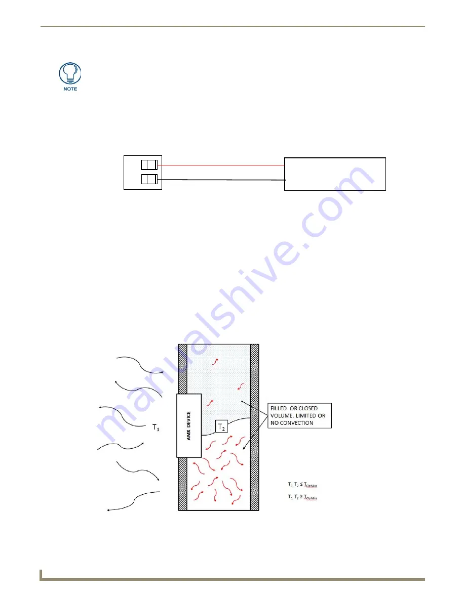
FIG. 10 shows an AMX device installed in a wall with a filled volume (such as with insulation or concrete), as well as
with a closed volume (such as between studs in an otherwise finished wall). The diagram shows how heat generated by
the device or other devices may have no way to escape, and may build up to levels that may affect device operation.
Connecting power to the MXT-1901-PAN should be done using the included 2-pin
3.5mm captive wire connector included with the device. This connector is retained
within its port with locking screws instead of the pins on each side of standard captive
wire connectors, and using force to insert a standard captive wire connector may
damage the device.
FIG. 9
NetLinx power connector wiring diagram
FIG. 10
Heat convection in filled or closed volume, limited or no convection
PWR +
GND -
To the Touch Panel
Power Supply


