background image

Installation

8

AXR-NWS NetWave Server

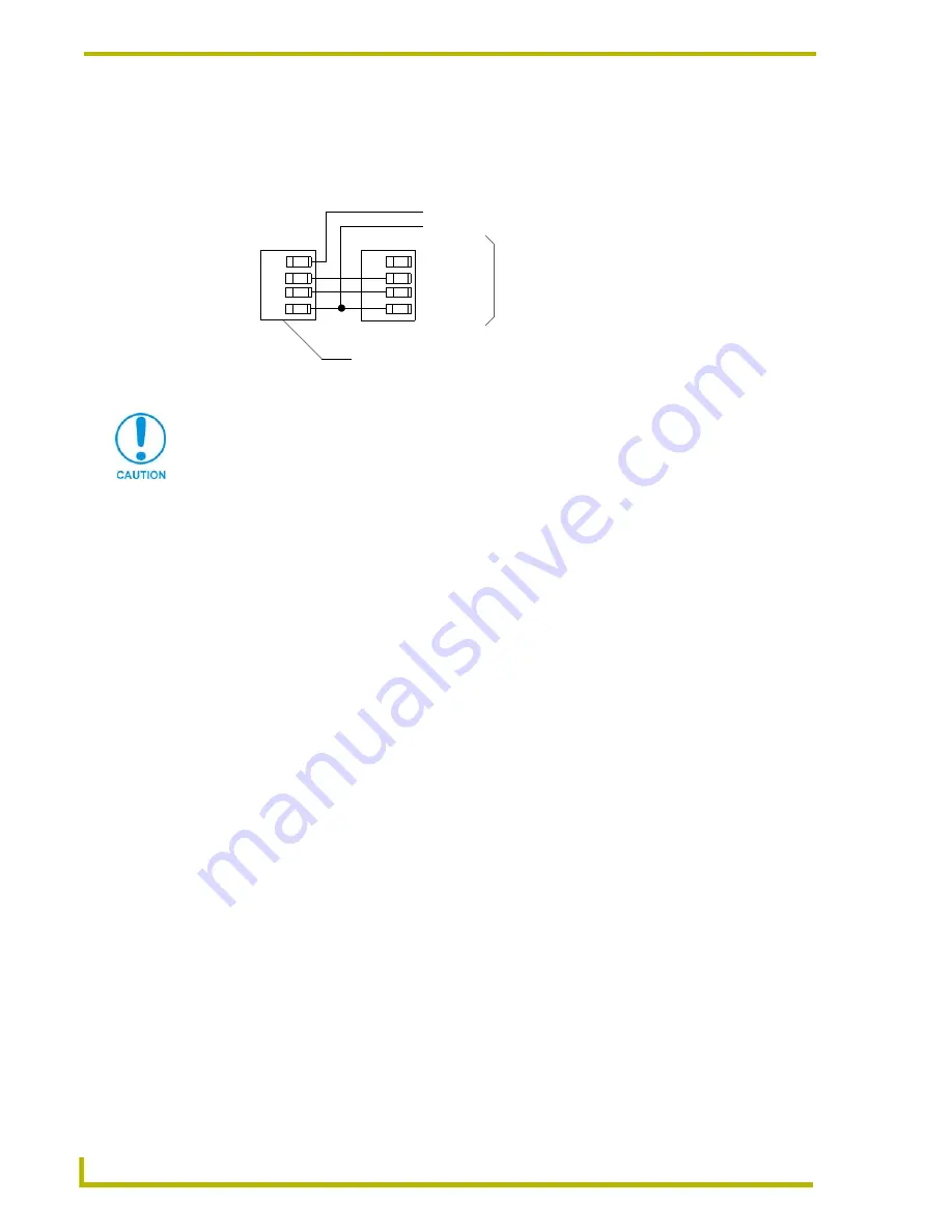
Using AXlink for data with an auxiliary power supply

Connect the Controller’s AXlink connector to the AXlink connector on the rear panel of the AXR-

NWS, as shown in FIG. 6.

Use an auxiliary 12 VDC power supply when the distance between the Central Controller and 

Server exceeds the limits described in Wiring Guidelines table. Connect only the GND (-) wire on 

the AXlink connector when using an auxiliary 12 VDC power supply.

Preparing captive wires

1.

Strip 0.25" of wire insulation off the ends of all wires. 

2.

Insert each wire end into the appropriate opening on the connector according to the wiring 

diagrams and connector types described in the

Using AXlink for data and power

section on 

page 7. Do not tighten the screws excessively; doing so may strip threads and damage the 

connector.

Installing the Control System

1.

Install the AXR-NWS on any flat surface.

2.

Rotate the RF antenna to a vertical position to communicate with the touch panels.

3.

Verify that the Server DIP switch settings are configured with the correct GROUP ADDRESS 

and GROUP ID.

4.

Verify the touch panels have the same GROUP ID value as the Server.

5.

Connect the Server to the Central Controller (FIG. 7) by connecting the 3.5 mm 4-pin AXlink 

cable from the bus connector to the AXlink connector at the rear of the Central Controller.

FIG. 6  

AXlink and 12 VDC power supply wiring diagram

PWR (+)

AXP

AXM
GND (-)

PWR (+)
AXP
AXM

GND (-)

AXR-NWS (3.5 mm connector)

Controller

PWR (+)
GND (-)

12 VDC power supply

If you are not using power from AXlink, disconnect the wiring from the Controller 
before wiring the AXR-NWS. Make sure the auxiliary power supply’s PWR (+) is not 
connected to the Central Controller’s AXlink connector.

Содержание AXR-NWS

Страница 1: ...instruction manual Control Panel Accessories AXR NWS NetWave Server ...

Страница 2: ... liability applies whether damages are sought or a claim is made under this warranty or as a tort claim including negligence and strict product liability a contract claim or any other claim This limitation of liability cannot be waived or amended by any person This limitation of liability will be effective even if AMX Corporation or an authorized representative of AMX Corporation has been advised ...

Страница 3: ... panel 5 Setting the Group ID 6 Setting Group ID DIP switches 6 Setting the Group ID on the touch panel 6 Connecting to the Controller 7 Power guidelines 7 Using AXlink for data and power 7 Using AXlink for data with an auxiliary power supply 8 Preparing captive wires 8 Installing the Control System 8 Installing the Optional NWA EXT External Extended Range Antenna 9 Firmware Upgrades 11 Replacing ...

Страница 4: ...ii AXR NWS NetWave Server Table of Contents ...

Страница 5: ...ized matte finish Operating Frequency 2 4 GHz RF digital spread spectrum transmission and reception with up to 16 ViewPoints Control Compatibility Axcess Central Controllers NetLinx Central Controllers Landmark Controller Front Panel Components AXlink LED Green LED that shows power and AXlink communication activity Blink patterns include Off No power or the controller is not functioning properly O...

Страница 6: ...ions Cont Connectors 4 pin male AXlink 3 5 mm bus connector connects to the Central Controller for receiving and transmitting AXlink control data and 12 VDC power Optional Accessories AC RK Rack Mount Kit PSN2 8 Power Supply NWA EXT External Netwave Antenna ...

Страница 7: ... any combination to communicating ViewPoint touch panels The AXR NWS allows a maximum control of 1020 channels An example is shown in FIG 1 FIG 1 AXR NWS control compatibility ViewPoint Touch Panels GROUP ADDRESS 1 255 Device Address 128 131 Device Address 132 135 Device Address 136 139 Device Address 140 143 ViewPoint Device 1 255 channels Device 2 255 channels Device 3 255 channels Device 4 255 ...

Страница 8: ... The GROUP ID DIP switch sets the identification number to synchronize communication between the wireless devices and AXR NWS Each AXR NWS must have a unique GROUP ID number All ViewPoints must match the four position DIP switch on the AXR NWS FIG 2 illustrates the relationship between Group Address and Device Address To use 32 wireless devices use two AXR NWS Servers set to two different Group ID...

Страница 9: ...IP switch value into the Device Number field and the DIP switch on the right shows the corresponding switch arrangement 8 Set the GROUP ADDRESS DIP switch on the AXR NWS to begin at the value assigned to the first device Setting the Device Address on a touch panel 1 Press SETUP on the Main page of the touch panel 2 Press PROTECTED SETUP on the Setup page to open the password keypad 3 Enter 1988 de...

Страница 10: ...ermine the number of devices to be controlled 2 Verify the desired device number values are not assigned to another device 3 Determine the number of AXR NWS Servers needed to control the wireless devices These devices are assigned addresses in groups of 16 each group is then assigned a GROUP ID Use the DIP switch values shown in the above Group ID DIP Switch Values table to set the GROUP ID on the...

Страница 11: ...ut Using AXlink for data and power Connect the AXlink connector to the AXlink port on the rear of the AXR NWS for data and power FIG 5 using mini and standard 4 pin captive screw type connectors FIG 4 ViewPoint wireless settings page Wiring Guidelines Wire Size Maximum Wiring Length 18 AWG 670 69 ft 204 42 m 20 AWG 424 33 ft 129 33 m 22 AWG 264 55 ft 80 63 m 24 AWG 166 76 ft 50 83 m Servers should...

Страница 12: ...e screws excessively doing so may strip threads and damage the connector Installing the Control System 1 Install the AXR NWS on any flat surface 2 Rotate the RF antenna to a vertical position to communicate with the touch panels 3 Verify that the Server DIP switch settings are configured with the correct GROUP ADDRESS and GROUP ID 4 Verify the touch panels have the same GROUP ID value as the Serve...

Страница 13: ...Controller rear view Mini AXlink connector 3 5 mm AXR NWS rear view The AXR NWS does not support devices which previously used the AXR WAVES server AXR NWS uses a 2 4 GHz digital spread spectrum to avoid common problems associated with RF control However avoid placing the AXR NWS components next to microwave ovens spread spectrum consumer microwave video link transceivers projectors using Halide X...

Страница 14: ...Installation 10 AXR NWS NetWave Server ...

Страница 15: ...lide the rear plate circuit board assembly out of the AXR NWS housing 5 Pry the firmware chip from its socket by placing a non conducting flat blade tool between the firmware chip and its mounting socket 6 Place the new firmware chip in the mounting socket Ensure the pins on the firmware chip and the socket slots are aligned correctly Apply sufficient pressure to the chip to seat it in the socket ...

Страница 16: ...ecure the antenna to the rear coaxial connector in a counter clockwise direction Refer to the Installing the Optional NWA EXT External Extended Range Antenna section on page 9 for more detailed information on connecting the optional external antenna ...

Страница 17: ...Installation 13 AXR NWS NetWave Server ...

Страница 18: ...ive richardson TX 75082 USA 469 624 8000 800 222 0193 fax 469 624 7153 technical support 800 932 6993 042 004 2258 5 03 2003 AMX Corporation All rights reserved AMX the AMX logo the building icon the home icon and the light bulb icon are all trademarks of AMX Corporation AMX reserves the right to alter specifications without notice at any time In Canada doing business as Panja Inc ...

Отзывы: