


Welcome.
Thank you for buying an
IBM server.
This server
contains information for setting
up and configuring your server.
For detailed information
about your server, view the
on the
You can also find the most
current information about your
server on the IBM Web site at:
http://www.ibm.com/servers/
eserver/support/xseries/
index.html
Installation Guide
User's Guide
Documentation CD.
Installation Guide
System x3200
Types 4362 and 4363
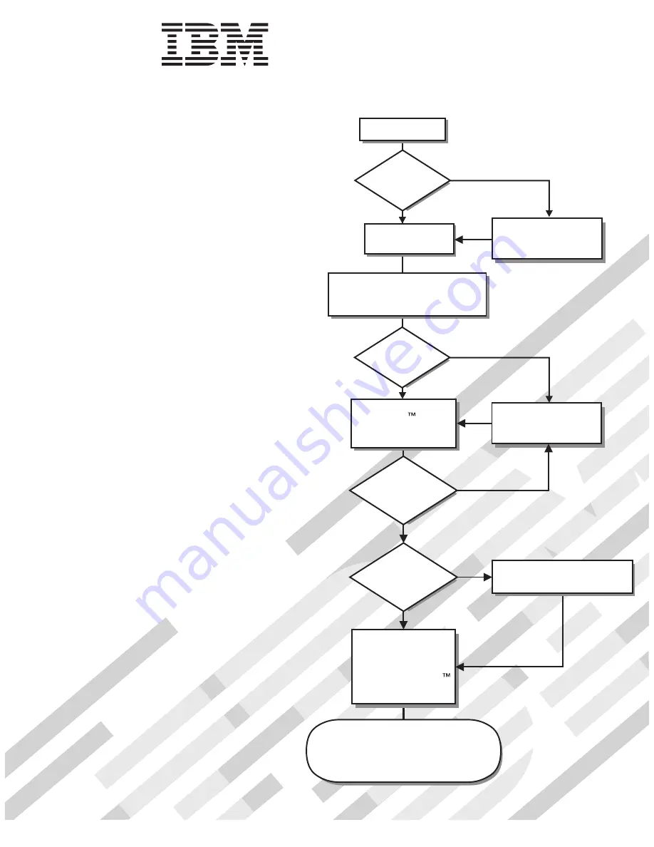
Turn off the server
and install options.
Did the server
start correctly?
Yes
No
Go to the Server Support
flow chart on the reverse
side of this page.
Start the server.
Did the server
start correctly?
Yes
No
Cable the server and options;
then, restart the server.
Was the
server setup
completed?
Use
ServerGuide to
install the operating
system?
The server is ready to use.
Go to
to register the server.
http://www.ibm.com/support/mysupport/
Go to the Web for instructions:
http://www.ibm.com/support/
No
Yes
Yes
No
Use the IBM
ServerGuide program
to set up and
configure hardware.
Go to the Server Support
flow chart on the reverse
side of this page.
Install applications,
such as IBM systems
management software
and IBM ServeRAID
programs
Содержание x3200 - System M3 - 7328
Страница 3: ...System x3200 Type 4362 and 4363 Installation Guide...
Страница 56: ...42 System x3200 Type 4362 and 4363 Installation Guide...
Страница 99: ......
Страница 100: ...Part Number 43W6955 Printed in USA 1P P N 43W6955...


