


Welcome.
Thank you for buying an
IBM server.
This server
contains information for setting
up and configuring your server.
For detailed information about
your server, view the documentation
on the IBM System
You can also find the most
current information about
your server at
http://www.ibm.com/systems/support/
Your server
is based on the X-Architecture
technology, and it features
superior performance, availability,
and affordability.
CD.
Installation Guide
Documentation
Installation Guide
System x3500
Type 7977
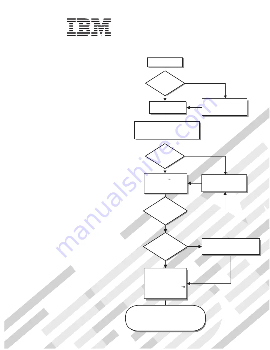
Turn off the server
and install options.
Did the server
start correctly?
Yes
No
Go to the Server Support
flow chart on the reverse
side of this page.
Start the server.
Did the server
start correctly?
Yes
No
Cable the server and options;
then, restart the server.
Was the
server setup
completed?
Use
ServerGuide to
install the operating
system?
The server is ready to use.
Go to
to register the server.
http://www.ibm.com/support/mysupport/
Go to the Web for instructions:
http://www.ibm.com/systems
/support/
No
Yes
Yes
No
Use the IBM
ServerGuide program
to set up and
configure hardware.
Go to the Server Support
flow chart on the reverse
side of this page.
Install applications,
such as IBM systems
management software
and IBM ServeRAID
programs
Summary of Contents for x3500 - System - 7977
Page 3: ...IBM System x3500 Type 7977 Installation Guide...
Page 14: ...xii IBM System x3500 Type 7977 Installation Guide...
Page 48: ...34 IBM System x3500 Type 7977 Installation Guide...
Page 76: ...62 IBM System x3500 Type 7977 Installation Guide...
Page 118: ...104 IBM System x3500 Type 7977 Installation Guide...
Page 122: ...108 IBM System x3500 Type 7977 Installation Guide...
Page 123: ......
Page 124: ...Part Number 44R5218 Printed in USA 1P P N 44R5218...


