


AMW 12_00
15
C
C
O
O
N
N
N
N
E
E
C
C
T
T
I
I
O
O
N
N
S
S
H
H
O
O
T
T
W
W
A
A
T
T
E
E
R
R
B
B
A
A
T
T
T
T
E
E
R
R
Y
Y
GENERAL
Type of unit
65
²92M-100
140-142M
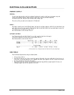
Nominal output *
kW
7
9
13
Nominal flow
l/h
277
356
517
Pressure loss
kPa
1,68
2,64
5,94
* At 80°C WT° and 20°C AT°
Used to keep the ambient area to temperature or bring this to temperature depending on capacity.
The hot-water battery (LPHW) is fitted on the pulse side of the unit.
The connection of the LPHW is on the right of the unit.
The LPHW must be connected to the CH boiler by a registered installer. The unit is not fitted with a circulating
pump. This must be fitted by the CH fitter and adapted to the capacity of the LPHW. The incorporated control can
be used to control the circulating pump and/or the CH boiler.
The unit can also optionally be equipped with a three-way valve
HYDRAULIC CONNECTIONS
Fitted with ½” nipple connection to the LPHW.
The optional three-way valve
is ½” external.
On the LPHW, the IN and OUT are marked
LPHW IN
and
LPHW OUT
CONTROL
ELECTRICAL CONNECTIONS/ SEE DIAGRAM
The LPHW is controlled independently of the CH via the built-in 24V = control. When the dehumidifier functions, the
fan also moves air over the LPHW.
The thermostat (TH) or hygrothermostat (HYTH)
orders the unit control to provide heat. The fan and circulation
pump are controlled by the PCB. A non-return valve should be fitted in the hydraulic circuit.
In order to prevent hot water flowing through when the swimming pool area is on temperature, one can apply a
built-in three-way valve.
ADVANTAGE: on heat demand, the three-way valve opens and water flows directly through the LPHW,
immediately providing heat.
W
W
H
H
E
E
N
N
R
R
E
E
O
O
R
R
D
D
E
E
R
R
E
E
D
D
P
P
L
L
E
E
A
A
S
S
E
E
G
G
I
I
V
V
E
E
T
T
Y
Y
P
P
E
E
O
O
F
F
U
U
N
N
I
I
T
T
A
A
N
N
D
D
C
C
A
A
P
P
A
A
C
C
I
I
T
T
Y
Y
O
O
F
F
L
L
P
P
H
H
W
W
.
.
Содержание 100
Страница 1: ......
Страница 2: ......
Страница 4: ......
Страница 8: ......
Страница 18: ...14 AMW 12_00 I IN NS ST TA AL LL LA AT TI IO ON N E EX XA AM MP PL LE E ...


