


22
AMW 12_00
E
E
L
L
E
E
C
C
T
T
R
R
I
I
C
C
A
A
L
L
D
D
A
A
T
T
A
A
A
A
N
N
D
D
S
S
U
U
P
P
P
P
L
L
I
I
E
E
S
S
P
P
O
O
W
W
E
E
R
R
S
S
U
U
P
P
P
P
L
L
Y
Y
GENERAL
All units are equipped with an electric switchboard cabinet with control circuit board, compressor relay and
connection terminals. External control equipment should be ordered and installed separately.
All controls are 24VDC and thus of the ultra low safety voltage type.
The units are fully pre-wired and constructed to CE standard.
SUPPLY
The supply connection must be sufficiently heavy to supply the complete capacity: both for the unit itself and for any
extra consumers such as a second fan. Electrical heating and electrical defrost have a separate supply connection.
The voltage must be adapted to the type of unit.
See technical sheet on the outside of the unit.
AUTOMATIC SYSTEM
A multi-polar automatic unit with at least 3 mm contact opening is placed on the supply.
This must be adapted to the maximum current strength of the unit.
See technical sheet on the outside of the unit.
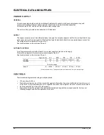
Type of unit
65
92M
100
140
142M
Voltage
V
230
230
3x400+N
3x400+N
230
Nominal
A
6
9,9
4,1
4
11,4
To be foreseen
Fuses *
A
2P 20A
2P 20A
4P 20A
4P 20A
2P 25A
*
Always use slow fuses. Three-phase fuses must always be a four pole automatic type.
C
C
O
O
N
N
T
T
R
R
O
O
L
L
S
S
Thermostats and hygrostats should generally be placed:
120 cm above the floor
Preferably in a dead corner of the room and/or against a flat wall so they are not affected by the air blown out
of the units (i.e. not immediately next to or opposite the outlet), by draughts or other hot or cold air movements.
As far as possible from the unit in other cases.
Always check if wall ducts and tubes behind thermostats and hygrostats are properly sealed: the here out
following draught can affect the operation of the units.
Содержание 100
Страница 1: ......
Страница 2: ......
Страница 4: ......
Страница 8: ......
Страница 18: ...14 AMW 12_00 I IN NS ST TA AL LL LA AT TI IO ON N E EX XA AM MP PL LE E ...


