background image


Page 35 

EVACU ELITE


INSTALLATION, COMMISSIONING AND USER MANUAL 

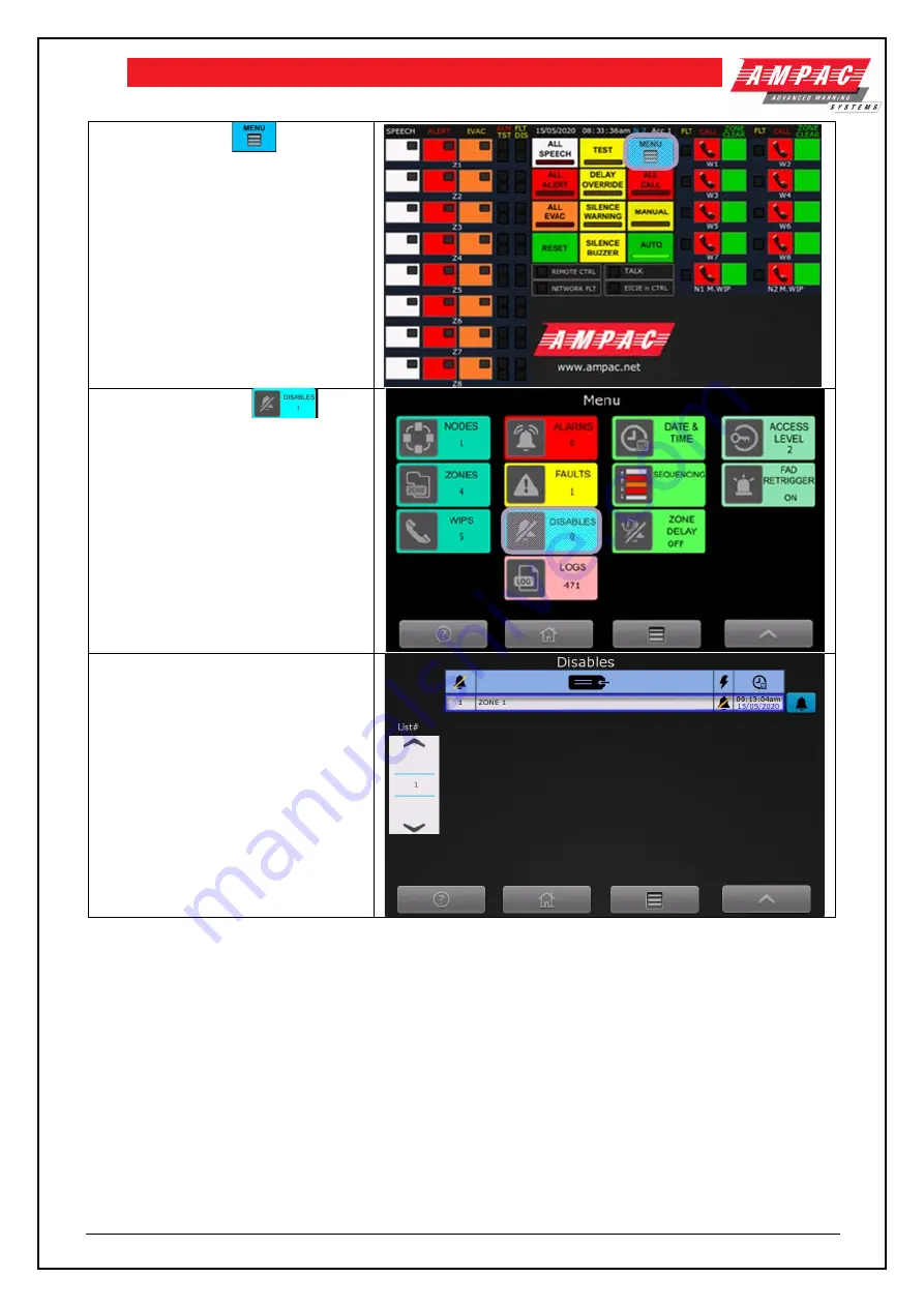
Activate the MENU 

 control 


Activate the DISABLE 

control 


Screen display the list of disabled 

zones, and  details the date and time 

when the zone was disabled. 


5.4.6  Activating the Test Tone 


A test tone can be activated in an emergency zone. 


Содержание EvacU Elite

Страница 1: ...EvacU Elite Emergency Warning Intercom System EWIS Install Commission and User Manual MAN3137 2 ...

Страница 2: ...Line EWS and EIS 23 5 1 3 Automatic Manual Mode control and Indication EWS 23 5 1 4 Test condition control EWS 24 5 1 5 Silence warning control and indicator EWS 24 5 1 6 Reset control EWS 25 5 1 7 All controls and indicators EWS 25 5 1 8 Silence buzzer control EWS and EIS 26 5 1 9 Delay override EWS 26 5 1 10 All call control and indicator EIS 27 5 1 11 Menu control EWS and EIS 27 5 1 12 Individu...

Страница 3: ...ss levels 42 6 3 Nodes 43 6 3 1 Distribution CPU card 45 6 3 2 Network interface card 46 6 3 3 Multi purpose interface card 47 6 3 4 Multi purpose output card 49 6 3 5 Quad radial EIS line card 50 6 3 6 Dual loop EIS line card 52 6 3 7 Dual 25 watt amplifier card 54 6 3 8 50Watt amplifier card 56 6 3 9 Graphical user interface 56 6 3 10 Power supply 57 6 4 Zones 59 6 5 WIPs 60 6 6 Alarms 61 6 7 Fa...

Страница 4: ...8 3 Field wiring 97 8 9 Dual loop EIS line card 98 8 9 1 Connections 98 8 9 2 Indicators 98 8 9 3 Field wiring Use of Ferrites on each Loop WIP card 99 8 10 Network Interface Card 101 8 10 1 Connectors 101 8 10 2 Indications 101 8 10 3 Setting the node address 102 8 10 4 Field wiring 103 8 11 Cable Terminations and Routing 110 9 Maintenance 114 10 Specification 115 10 1 General 115 10 2 Graphical ...

Страница 5: ...12 Definitions 121 ...

Страница 6: ...anel with the individual EIS controls and indicators highlighted 28 Figure 5 6 WIP handset with controls highlighted 29 Figure 5 7 WIP handset with indicators highlighted 29 Figure 5 8 LED Indicators 30 Figure 6 1 Main menu screen 42 Figure 6 2 Access level screen 43 Figure 6 3 Distribution CPU card status screen 45 Figure 6 4 Distribution CPU card status 46 Figure 6 5 Input status 46 Figure 6 6 D...

Страница 7: ...t and battery isolator 77 Figure 8 1 Label 3203 detailing terminations for each card type 79 Figure 8 2 MIC wiring standard 83 Figure 8 3 MIC wiring voltage reversal 84 Figure 8 4 Dual 25Watt amplifier wiring 89 Figure 8 5 50Watt amplifier wiring 92 Figure 8 6 50Watt amplifier wiring 94 Figure 8 7 Quad radial EIS wiring 97 Figure 8 8 Dual loop EIS wiring 100 Figure 8 9 Network wiring side by side ...

Страница 8: ...ormation EVACU ELITE EMERGENCY WARNING AND INTERCOMMUNICATION SYSTEM MANUFACTURED BY AMPAC Pty Ltd 7 LEDGAR RD BALCATTA WA 6017 WESTERN AUSTRALIA PH 61 8 9201 6100 FAX 61 8 9201 6101 www ampac net CONFORMS TO AS 4428 16 AS 4428 4 AS 7240 4 ACTIVFIRE CERTIFICATE OF COMPLIANCE NUMBER ...

Страница 9: ...428 4 Fire Detection Warning Control and Intercom Systems Control and indicating Equipment Part 4 Emergency intercom control and indicating equipment AS 4428 16 Fire Detection Warning Control and Intercom Systems Control and indicating Equipment Part 16 Emergency warning control and indicating equipment AS 7240 4 Fire detection and alarm systems Part 4 Power supply equipment AS 1670 4 Fire Detecti...

Страница 10: ...e access levels for the indications and controls relating to mandatory functions Section 5 details the controls and indicators and specifies the required access level for each control There are four access levels Access level 1 is used by persons having a general responsibility for safety supervision All mandatory indications are visible at access level 1 without prior manual intervention This is ...

Страница 11: ...tem X O O 7 9 2 Silencing the emergency warning condition with a manual control M O O 7 10 1 Reset of the emergency warning condition from the emergency detection system X O O 7 10 2 Reset of the emergency warning condition with a manual control M O O 7 11 Output to warning devices M M O 7 12 Emergency warning condition output signal M O O 8 3 4 Faults related to emergency zones M M M 8 3 5 Earth ...

Страница 12: ... the EvacU ELITE 3 4 Emergency intercom control and indicating equipment The following optional clauses of AS 4428 4 are supported by the EvacU Elite Clause 8 8 External silencing of the EICIE Fault Condition Clause 9 0 Zone Cleared Condition Clause 10 0 Manual Control of Networked EICIE Clause 11 2 WIP group call control up to 6 handsets including the EICIE handset ...

Страница 13: ...hical user interface housed in a metal cabinet The cabinet is available in two cabinet sizes 13U and 24U Both cabinets can accommodate a FireFinder PLUS in the top section when a COMBO solution is required Figure 4 1 EvacU ELITE and FireFinder PLUS 24U COMBO unit external view Figure 4 1 above shows an external view of the EvacU ELITE and FireFinder PLUS The cabinet size is 24U Cabinet has been de...

Страница 14: ...ached to the DCPU in the first rack only BRD63MOCx A MOC Multi purpose output card BRD63MICx A MIC Multi purpose interface card BRD63LPAx A LPA Dual 25W amplifier BRD63LPAx B LPA 50W amplifier BRD63HPAx B HPA 150W amplifier See Note 1 BRD63ILCx A ILC Quad radial EIS line card BRD3LILC LILC Dual loop EIS line card Note 1 items not covered by LPCB certification at this point in time The number and t...

Страница 15: ...he all purpose back plane with the dedicated DCPU connector on the left and 16 card connectors The vertical connectors on the left hand side are used to connect all purpose backplanes together The first rack lowest position in the cabinet connects to the power distribution board refer to section 4 2 2 Figure 4 3 Front view of the universal rack Figure 4 3 shows a front view of the universal rack w...

Страница 16: ...ehind the cable ducting for air circulation 4 2 2 Power Supply 4 2 2 1 General Power supply consists of up to three power supply modules the 13U cabinet can accommodate 2 power supply modules The first module which is always fitted is referred to as the primary and controls the charging of the batteries and the second and third modules are secondary units which are fitted depending on the alarm cu...

Страница 17: ...PSU fault bus fault charger damage EWCIE Power controls the power to the EvacU ELITE Indicator lit when power is available FDCIE Power controls the power to the FireFinder PLUS Indicator is lit when power is available Battery Charger LED Indication Condition Off On batteries or no power Green steady Battery is charged greater than 80 Green flashing Battery is charging Yellow flashing If mains on c...

Страница 18: ...le Green flashing Mains is off running from the standby power source Yellow flashing Fault for example blown fuse incorrect checksum PSU fault bus fault charger damage EWCIE Power indicator lit when power is available to the EWCIE 4 2 2 3 Power Distribution Board The power distribution board routes the power from the power supply modules to the cards mounted in the universal racks and provides ter...

Страница 19: ...backplane CN2 connects to the primary power supply module and CN3 and CN4 connect to the secondary power supply modules TB1 and 2 connect to the standby power source batteries TB3 is the connection to the air circulating fans TB4 is the connection to a temperature sensor sited adjacent to the batteries temperature of the batteries is required so the batteries can be charged to the manufacturer s s...

Страница 20: ...3 EVACU ELITE INSTALLATION COMMISSIONING AND USER MANUAL Figure 4 9 Three power supply modules connected to the power supply distribution board Figure 4 10 Power supply showing the primary power supply module ...

Страница 21: ...terface The GUI provides the user interface via one or more colour touch screens and a LED membrane Figure 4 11 Main GUI and LED membrane The Main GUI has the system wide controls and individual controls for emergency zones and WIP handsets according to the site specific data Where more individual controls are required additional secondary GUIs are added The 13U cabinet supports 3 GUIs and the 24U...

Страница 22: ...ated to the front panel MCP and input 4 is dedicated to the door switch Third party FDCIE Isolated RS 485 link to interface to third party FDCIE Graphics interface RJ45 1 Connection to Distribution CPU RJ45 2 Connection to Slave GUI 4 2 4 Universal Rack Cards The following are the universal rack cards 4 2 4 1 Distribution CPU Each rack has a dedicated slot for a DCPU The DCPU has the link to the G...

Страница 23: ...row COM NO NC Mini USB For future use RJ45 1 Provides a CAT5 6 network connection to the front panel GUI RJ45 2 Redundant CAT 5 6 ethernet connection to the front panel GUI Remote paging consoles 4 2 4 2 Multi purpose output card Occupies one slot Provides eight single ended supervised outputs suitable for driving alarm warning devices such as strobes VADs or vibrating pads Each pair of outputs ca...

Страница 24: ...Figure 4 15 Multi purpose interface card Input 1 2 3 and 4 Single ended inputs common floating reference with selectable EOL Input 5 6 and 7 Differential inputs individual floating reference with selectable EOL Input 8 Differential input with floating reference with fault feedback user selectable resistance Relay 1 and 2 Single pole double throw COM NO NC Serial RS232C serial port with CTS and RTS...

Страница 25: ...Hz 200 Hz to 12kHz 3dB w r t 1kHz SNR 70db Speaker Circuit Monitoring DC nominal 47kΩ 4 2 4 5 50Watt Amplifier Card Occupies two slots Provides one 50watt audio output with DC monitoring Figure 4 17 50 watt amplifier Max Drive Voltage 100V rms full load Distortion 0 1 50 Watt Frequency Response AS 4428 16 400 Hz to 10kHz 1dB w r t 1kHz 200 Hz to 12kHz 3dB w r t 1kHz SNR 70db Speaker Circuit Monito...

Страница 26: ...emaining audio outputs 2 3 and 4 are rated at 75watt max each Note 1 items not covered by LPCB certification at this point in time Figure 4 18 150 way amplifier Max Drive Voltage 100V rms full load Distortion 0 3 150Watt x1 Frequency Response AS 4428 16 300 Hz to 10kHz 1dB w r t 1kHz 150 Hz to 12kHz 3dB w r t 1kHz SNR 70db Speaker Circuit Monitoring DC nominal 47kΩ 4 2 4 7 Quad Radial EIS line car...

Страница 27: ...edance 600Ω bandwidth 3K4 Hz 4 2 4 8 Dual Loop EIS line card Occupies one slot Provides 2 individually supervised fault tolerant loop interfaces for handsets and associated manual call points Each loop supports up to 20 handsets with associated manual call points Figure 4 20 Dual loop EIS line card LOOP 1 2 IN OUT Inputs for Ampac EvacU ELITE Loop WIP handsets Up to 2 Ampac MCPs can be connected t...

Страница 28: ...up to 500m Requires SFP OEM3097 Single Mode Fibre optic using single fibre OEM3095 and OEM3096 or dual fibre OEM3094 for distances up to 10000m Side A Side B Description OEM3087 OEM3088 VDSL 2 core copper cable for distances up to 1000m OEM3094 N A Single mode dual fibre for distances up to 10000m See Note 1 OEM3095 OEM3096 Single mode single fibre for distances up to 10000m OEM3097 N A Multi mode...

Страница 29: ...LATION COMMISSIONING AND USER MANUAL Figure 4 22 Detail on fitting the SFP module to the NIC for VDSL Connection 2 core copper To set the node address refer to section 8 10 3 For networking wiring examples refer to section 8 10 ...

Страница 30: ...f each control and indicator and the applicable system EWS or EIS 5 1 2 Status Line EWS and EIS The status line details the following Date 15 05 2020 Time 08 33 Node No 2 Access level 1 common to the EWCIE and EICIE refer to section 3 2 5 1 3 Automatic Manual Mode control and Indication EWS The EWS shall be in the automatic or manual mode In the automatic mode the EWS automatically responds to ala...

Страница 31: ...s in MANUAL mode then the REMOTE CTRL indicator is illuminated at All EWCIE except the EWCIE that is in control Refer to section 5 1 14 5 1 4 Test condition control EWS The yellow indicator is illuminated steady when the EWCIE is in the test condition To place the EWCIE in the test condition activate the TEST control at access level 2 or higher The test condition is system wide meaning all configu...

Страница 32: ...All controls and indicators EWS The EWCIE has 3 All controls and associated indicators All speech All alert All evac 5 1 7 1 All speech control and indicator The red indicator is illuminated steady when the EWIS is in All Speech and all emergency zones are selected for live speech To place the EWCIE in All Speech activate the ALL SPEECH control at access level 2 or higher The EWCIE must be in the ...

Страница 33: ...heir individual alert status indicators Emergency zone 4 is set to Evacuation causing emergency zone 4 to broadcast the evacuate warning signal and update its status indicators from alert to evacuate All alert control is activated which cancels the All Alert state This causes the All Alert indicator to be extinguished all the emergency zones to extinguish their individual alert indicator and to st...

Страница 34: ... EWS and EIS Activating the Menu control at access level 2 will display the main menu screen Refer to section 5 6 for further detail 5 1 12 Individual EWS controls and indicators Refer to the highlighted section in figure 5 2 for the individual EWS controls Figure 5 2 Front control panel with individual EWS controls and indicators highlighted Each emergency zone in the EWS has its own controls and...

Страница 35: ...y zone for speech activate the speech control at access level 2 when the EWS is in MANUAL mode ALERT indicator is illuminated RED when the alert warning signal is being broadcast to the emergency warning zone To manually broadcast the alert warning signal activate the ALERT control To cancel the broadcast activate the ALERT control EVAC indicator is illuminated RED when the evacuate warning signal...

Страница 36: ...gain Control is only active when the master handset is off hook Figure 5 7 WIP handset with indicators highlighted There are three indicators associated with WIP handset FLT Illuminated when there is a fault associated with the WIP handset and associated transmission path CALL indicator flashes red when a call is being established to a WIP handset or there is an incoming call from a WIP handset ZO...

Страница 37: ...can be added Refer to the Programming Manual for further information 5 3 Led Indicators The EWCIE is fitted with the following LED indicators Figure 5 8 LED Indicators 5 3 1 Power Power power is applied to the EWCIE 5 3 2 Power Fault Power Fault fault associated with the PSE loss of mains loss of standby power source battery charger fail and high battery impedance 5 3 3 Fault Fault EWCIE or EICIE ...

Страница 38: ...to broadcast live speech in automatic or manual mode Refer to section 5 1 3 To broadcast live speech at any time the emergency zones must be selected by using the ALL SPEECH control refer to section 5 1 7 1 for all emergency zones or using the individual SPEECH controls refer to section 5 1 12 Once the emergency zones have been selected the PTT control on the microphone is activated and any audio ...

Страница 39: ...o or visual broadcast or both Refer to section 5 1 5 5 4 3 3 Reset To stop the phasing and silence the broadcast of emergency signals the EWS can be reset from the emergency warning condition using the RESET control Refer to section 5 1 6 The emergency warning condition must be silenced prior to operating the RESET control Note if alarm signals are present when the reset operation is complete then...

Страница 40: ... information on setting priorities 5 4 5 Disabling Emergency Zones There is a facility to disable one or more emergency zones When an emergency zone is disabled the emergency zone status indication Speech Alert Evac Fault and Test are extinguished the audio and visual outputs are de activated The individual emergency zone ALM indicator is unaffected See section 5 1 12 The system wide ALARM indicat...

Страница 41: ...N COMMISSIONING AND USER MANUAL To Disable Zone 1 activate the control on the Zones screen On the Zone Settings screen activate the control Zone setting screen updated to show the disable 5 4 5 2 To view the disabled emergency zones ...

Страница 42: ...ND USER MANUAL Activate the MENU control Activate the DISABLE control Screen display the list of disabled zones and details the date and time when the zone was disabled 5 4 6 Activating the Test Tone A test tone can be activated in an emergency zone ...

Страница 43: ...Page 36 EVACU ELITE INSTALLATION COMMISSIONING AND USER MANUAL Activate the MENU control Activate the ZONE control To activate the test tone for zone 1 activate the control on the Zones screen ...

Страница 44: ... indications are unaffected The emergency zone TEST indicators are illuminated steady Refer to section 5 1 12 The system wide test indicator is illuminated steady see section 5 3 9 Activate the TEST control The main screen has been updated to show all emergency zones in the test condition and the TEST indicator is illuminated steady The EWS can now be placed in the manual mode and all call or indi...

Страница 45: ...E off hook 2 Confidence tone will be broadcast in the ear piece to indicate the EICIE has recognised the handset going off hook 3 Select the WIP handset to call by activating the appropriate Call control refer to section 5 1 13 4 The call indicator flashes and a ring tone replaces the confidence tone in the ear piece The buzzer on the selected WIP handset is pulsing matching the frequency of the r...

Страница 46: ... 4 Establishing a multi party conference call The EICIE supports a full duplex multi party conference call that supports up to 5 WIP handsets and the handset at the EICIE A single full duplex call is established refer to section 5 5 2 for EICIE handset to WIP handset and section 5 5 3 for WIP handset to EICIE handset If another WIP handset is taken off hook the corresponding Call indicator shall f...

Страница 47: ...s the EWS see clause 5 4 3 If the handset at an EICIE with a higher priority is taken off hook while the EIS is in use then the current calls in progress are transferred to the EICIE with the higher priority The WIP handsets that are off hook will revert to the ring tone and the calls can be established at the higher priority EICIE as required The handset at the lower priority EICIE is treated as ...

Страница 48: ...Page 41 EVACU ELITE INSTALLATION COMMISSIONING AND USER MANUAL 5 6 Remote Paging Console Currently not available ...

Страница 49: ...u screen Figure 6 1 Main menu screen 6 1 General The following controls are available on all screens Help Button Home screen reverts the display back to the default screen Back to the main menu screen Back to the previous screen 6 2 Access levels Refer to section 3 2 for detail on access levels The current access level of the node is displayed on the default screen refer to section 5 1 2 ...

Страница 50: ... ELITE is at access level 2 outer door open the following screen is displayed prompting the user to enter their UserID and password The access level is property of a UserID Figure 6 2 Access level screen Backspace button Enter Button 6 3 Nodes To access the Nodes screen the following controls are activated 1 Menu control 2 Node s control ...

Страница 51: ...ocated in rack 1 slot 0 To view the status of this card select the Distribution CPU icon Network interface card located in rack 1 slot 1 To view the status of this card select the Network interface card Icon Multi purpose interface card located in rack 1 slot 2 To view the status of this card select the Multi purpose interface card icon Multi purpose interface as above with a HLI fitted to the Fir...

Страница 52: ...n the inner door To view the status of this card select the Graphical user interface Icon Power supply located beneath rack 1 To view the status of this card select the Power supply Icon 6 3 1 Distribution CPU card The Distribution CPU card has 4 inputs and 3 outputs refer to section 4 2 4 1 The status screen for the Distribution CPU card shows the module status and the status of the 4 inputs as f...

Страница 53: ...he allocated zone description state status and action Figure 6 6 shows the status of the 3 outputs on the Distribution CPU note the icon is highlighted denoting outputs are displayed Figure 6 6 Distribution CPU card status showing the outputs There is a record for each of the 3 outputs showing the allocated zone number descriptor state status and action 6 3 2 Network interface card The status scre...

Страница 54: ...ype NIC PRIMARY the primary denotes that this NIC is the current primary of the network The location is Node 1 Rack 1 Slot 1 adjacent to the DCPU Software version 01 00 04 hardware version 00 01 000 and Status is Normal 6 3 3 Multi purpose interface card The multi purpose interface card has 8 inputs 2 outputs and a HLI to the FireFinder PLUS refer to section 4 2 4 3 The status screen for the Multi...

Страница 55: ... icon is not displayed Press to display the inputs The multi purpose interface card has 8 inputs Press to display the outputs The multi purpose interface card has 2 outputs Figure 6 10 Multi purpose interface card status Above is the module type MIC location Node 1 Rack 1 Slot 2 Software version 01 01 00 hardware version 15 15 255 and status is Normal The input record is the same as the Distributi...

Страница 56: ...g the output type allocated zone number descriptor state and status 6 3 4 Multi purpose output card The multi purpose output card has 8 outputs and outputs can be formed into pairs refer to section 4 2 4 2 The status screen for the Multi purpose output card shows the modules status and the status of the outputs as follows Figure 6 12 Multi purpose output card status screen ...

Страница 57: ...purpose output card status Above is the module type MOC location Node 1 Rack 1 Slot 3 Software version 01 00 06 hardware version 15 15 255 and status is in Fault Figure 6 14 Output status There is a record for each of the outputs showing the output type as analogue allocated zone number description state and status 6 3 5 Quad radial EIS line card The Quad radial EIS line card supports 4 handsets w...

Страница 58: ...the icon is highlighted Press to display the inputs Each handset supports one input Figure 6 16 Quad radial EIS line card status Above is the module type ILC location Node 1 Rack 1 Slot 4 Software version 01 00 14 hardware version 01 00 004 and status is Normal Figure 6 17 Handset status There is a record for each of the handsets showing the type as WIP allocated zone number description state and ...

Страница 59: ...tate and status 6 3 6 Dual loop EIS line card The Dual loop EIS line card supports 2 fault tolerant redundant loops with each loop supporting up to 20 WIP handsets Each handset supports an input which is normally interfaced to an MCP refer to section 4 2 4 8 The default status screen for the Dual loop EIS line card shows the modules status and the status of the configured handsets as follows Figur...

Страница 60: ...port Port 1 loop 1 out Port 2 loop 1 in Port 3 loop 2 out and Port 4 loop 2 in Figure 6 20 Dual loop EIS line card status Above is the module type LILC Loop Intercom Line Card Location is Node 1 Rack 1 Slot 16 Software Version 01 00 04 and hardware version 15 15 255 status is normal Figure 6 21 Handset status Above is the address of WIP handset Loop 1 of 2 Address is 01 of 20 on the loop reference...

Страница 61: ...ws both ports are inactive meaning the loop is inactive From Figure 6 19 there are no phones configured on the second loop For the loop status to be normal the loop has no faults and only Port 1 or 3 will be active If the loop has an interruption then the loop status will be open circuit and port 1 or 3 and 2 or 4 will be driving If the loop has a short circuit then the transmission path isolators...

Страница 62: ... 15 15 255 and status is Normal Figure 6 26 Amplifier status Above is the amplifier status The top field Output 1 is the descriptor The Audio field shows that this amplifier has BGM assigned The zone number assigned to the amplifier is shown and the denotes that the zone number is editable at access level 3 see 6 2 The Gain Type and Level show the relative volume setting for each of the assigned a...

Страница 63: ...mplifier card shows the modules status and the status of the amplifier as follows Figure 6 27 50 watt amplifier card status screen The display is identical to the Dual 25 watt amplifier card refer to section 6 3 7 except the Type of the module status is 50W Amp 6 3 9 Graphical user interface The graphical user interface card supports the touch screen and has 4 digital inputs The status screen is a...

Страница 64: ...tware version 01 00 07 hardware version 00 03 001 and status is Normal The input status is the same as the Multi purpose interface card refer to section 6 3 3 The first Graphical user interface fitted to a cabinet is the Primary and any other Graphical user interfaces fitted are referred to as Secondaries The secondaries do not have the inputs fitted and their Type is GUI SECONDARY 6 3 10 Power su...

Страница 65: ... the overall power status of the cabinet The node number PSU rating current system power current system voltage and system current is displayed Figure 6 32 Power supply module status Figure 6 32 details the status of each of the fitted power supply modules 24U cabinet supports up to 3 modules and the 13U cabinet supports up to 2 modules The status input voltage output voltage output current output...

Страница 66: ...igured in the system If there are any faults on a node there will be in the column Activate the control for detail on the zone 4 Individual Zone Screen Shows the status and configuration of the zone The control is used to disable enable the zone The control is used to turn on and off the test tone for the zone The volume of the test tone is set by the associated slider control The control is use t...

Страница 67: ...ccess the WIP screen the following controls are activated 1 Menu control 2 WIP control 3 WIP Screen Shows a list of WIP handsets configured in the system If there are any faults on WIP node there will be a in the column The control allows the WIP handset descriptor to be changed The column gives the physical location of the handset connection to the system Node Rack Slot input There are two WIP ha...

Страница 68: ... Shows a list of alarms The column zones the zone number in alarm The in the column indicates an alarm The column shows the date time of the alarm 6 7 Faults 1 Menu control 2 Fault control only if there is at least one fault present Control shows 3 faults conditions 3 Fault Screen Shows a list of faults The in the column indicates a fault The control will provide detail on the individual fault ...

Страница 69: ...detail for zone 2 and the audio output is in fault 5 Zone 3 Fault Detail Shows the detail for zone 3 and the audio output is in fault The faults can be also be viewed via the NODE screen 1 Menu control 2 Node s control 3 List of Node screen The associated with node 1 shows the fault is on Node 1 ...

Страница 70: ...creen the status of the module is missing 6 8 Disables 1 Menu control 2 Disables control only if there is at least one emergency zone disable Control shows 1 disable condition 3 Disable Screen Shows a list of zones that are disabled with a date and time tag The control will toggle the disable state 6 9 Logs To access the Logs screen the following controls are activated 1 Menu control ...

Страница 71: ...e logs Prompted to confirm clearing the logs 6 10 Date and Time To set the date and time the following controls are activated 1 Menu control 2 Date and time control require access level 3 3 Date and Time Screen Shows the current date and time and daylight saving details To set the time select the control To set the date select the control To turn daylight saving on off select the control ...

Страница 72: ... COMMISSIONING AND USER MANUAL To set the daylight saving start end time select the control To set the daylight saving start end date select the control 4 Setting the Time 5 Setting the Date 6 Setting daylight saving start or end time ...

Страница 73: ...g control requires access level 3 3 Sequence Screen Shows the sequence type the number of zones delay to alert and delay to evac The number of zones delay to alert and delay to evac are all parameters to the sequence type 4 Sequence type screen To set change the sequence type activate the control The and controls step thru the available sequences The cancels the action The accepts the selected seq...

Страница 74: ...the number of emergency zones The cancels the action The accepts the selected number of emergency zones 6 Delay to alert screen To set change the delay to alert activate the control The and controls step thru the hours minutes and seconds The cancels the action The accepts the displayed delay to alert 7 Delay to evac screen To set change the delay to evac activate the control The and controls step...

Страница 75: ...he alert signal after the Delay to Alert timeout has expired This continues until all zones are broadcasting the alert signal Evac Phased Evac Evac When an alarm signal assigned to an emergency zone and configured as type Evac is activated the associated emergency zone broadcasts the evac signal after the Delay to Evac timeout has expired After the broadcast has commenced the next Number of Zones ...

Страница 76: ...d Off Delays are programmed and currently switched On hence the Delay LED indicator is lit and the control states ZONE DELAY ON If the control is activated then the display is updated as below 3 Menu Screen after the ZONE DELAY control activated The Delay Led indicator will be extinguished 6 13 Access level The current access level is displayed on the Status Line see section 5 1 2 The access level...

Страница 77: ... Fire Alarm Devices FADs or warning devices are activated when the EWCIE enters the emergency warning condition see section 5 4 3 If the FAD retrigger is On and the EWS is silenced after entering the emergency warning condition and an alarm is reported in another emergency zone the FADs will be retriggered If the FAD retrigger is Off then the FADs will not be retriggered This facility is at access...

Страница 78: ...Page 71 EVACU ELITE INSTALLATION COMMISSIONING AND USER MANUAL ...

Страница 79: ...g any of the wiring or PCBs within the EvacU ELITE that you are correctly earthed The recommended method is to use an anti static wrist strap and flexible lead Fit the wrist strap to yourself and attached the flexible lead to the cabinet earth bolt located inside the top of the cabinet PCBs removed from the EvacU ELITE should be immediately placed in an anti static bag 7 3 Working on the system To...

Страница 80: ...Page 73 EVACU ELITE INSTALLATION COMMISSIONING AND USER MANUAL Figure 7 1 24U Cabinet Front and side view ...

Страница 81: ...Page 74 EVACU ELITE INSTALLATION COMMISSIONING AND USER MANUAL Figure 7 2 24U Cabinet Rear view showing mounting points Figure 7 3 24U Cabinet Top view showing the gland plate and cable entry ...

Страница 82: ...G AND USER MANUAL The 13U cabinet can be floor or wall mounted Refer to figure 7 4 7 5 ad 7 6 for cabinet dimensions fixing points and cable entry Figure 7 4 13U Cabinet Front and side view Figure 7 5 13U Cabinet Rear view showing mounting points ...

Страница 83: ...e mains is connected using the appropriately rated cable The mains cable should conform to one of the following standards AS CA S008 AS NZS 3191 AS NZS 5000 1 AS NZS 3808 or marked with VW 1 The circuit breaker in the 24U is rated at 25 amps and 16 amps for the 13U cabinet Recommended cable for the 24U is 2 5mm2 and 1 5mm2 for the 13U Following diagrams show the location of the mains isolator and ...

Страница 84: ...ation file If no configuration file has been created then the placement of the cards to the racks should be reflected in the configuration file NOTE Rack 1 is the bottom lowest rack Each rack must be fitted with a Distribution CPU If the configuration has multiple cabinets NIC required the NIC is fixed to the Distribution CPU in rack 1 7 7 Connecting the batteries Before connecting the batteries t...

Страница 85: ...3076 M10 lugs 25mm2 cable 3 175 amps CAB3077 M10 lugs 35mm2 cable 7 8 Recommended Batteries The maximum capacity battery that can be fitted to the 13U cabinet is 12V 100 AmpHr The maximum capacity battery that can be fitted to the 24U cabinet is 12V 190 AmpHr Certified 12VDC sealed lead acid batteries shall be used in the 13U and 24U EvacU ELITE cabinets As per IEC 62368 certified batteries shall ...

Страница 86: ... 8 2 Distribution CPU 8 2 1 Connections Following table details the field connections to the distribution CPU BGM 1 HOT 1 2 BGM 2 HOT BGM 1 COLD 3 4 BGM 2 COLD BGM 1 SHIELD 5 6 BGM 2 SHIELD INPUT 1 7 8 INPUT 1 REF INPUT 2 9 10 INPUT 2 REF RELAY 1 1 NO 11 12 RELAY 1 2 NC RELAY 1 1 COM 13 14 RELAY 1 2 COM RELAY 2 NO 15 16 RELAY 3 NC RELAY 2 COM 17 18 RELAY 3 COM RELAY 2 NC 19 20 RELAY 3 NC Mini USB ...

Страница 87: ...nd 2 are available for BGM and can be routed to any amplifier Inputs 1 and 2 are general purpose inputs Relays 1 2 and 3 are general purpose outputs 8 2 2 Indications The Distribution CPU has one status indicator located adjacent to RJ45 2 See below Status Indicator OFF cards have no power or processor is fault FLASHING GREEN board is operating no faults FLASHING AMBER board has a fault condition ...

Страница 88: ... voltage range 12 to 28VDC The outputs are typically used to drive VADs Applicable Ampac Item number are Ceiling Mount Item Number Description 4107 1101 VXB VC Ceiling mount white flash shallow white body 4107 1102 VXB VC Ceiling mount white flash deep white body 4107 1103 VXB VC Ceiling mount red flash shallow white body 4107 1104 VXB VC Ceiling mount red flash deep white body 4107 1105 VXB VC Ce...

Страница 89: ...te body 4107 1133 Dual VXB Ceiling mount red and amber flash shallow white body 4107 1134 Dual VXB Ceiling mount red and amber flash deep white body Cabling No of Devices 1 0mm2 Field Wiring 1 5mm2 Field Wiring 10 444m 620m 20 222m 310m 30 148m 207m 40 111m 155m 8 3 2 Indicators The Multi purpose output card MOC has one status indicator per output 8 and a general status indicator See below Output ...

Страница 90: ...Page 83 EVACU ELITE INSTALLATION COMMISSIONING AND USER MANUAL Figure 8 2 MIC wiring standard ...

Страница 91: ...Page 84 EVACU ELITE INSTALLATION COMMISSIONING AND USER MANUAL Figure 8 3 MIC wiring voltage reversal ...

Страница 92: ...On bus Input 1 2 3 and 4 Single ended inputs common floating reference with selectable EOL Input 5 6 and 7 Differential inputs individual floating reference with selectable EOL Input 8 Differential input with floating reference with fault feedback user selectable resistance Relay 1 and 2 Single pole double throw COM NO NC Serial RS232C serial port with CTS and RTS available Currently unused FACP A...

Страница 93: ...o power or processor is fault FLASHING GREEN board is operating no faults FLASHING AMBER board has a fault condition STEADY AMBER Not receiving commands from the Distribution CPU 8 5 Dual 25Watt amplifier 8 5 1 Connections Following table details the field connections for the Dual 25Watt amplifier ...

Страница 94: ... 54 Ceiling speaker 4 5W white low profile grommets 4113 1015 55 Ceiling speaker 4 5W black low profile grommets 4113 1016 56 Ceiling speaker 4 5W white low profile aluminium grill grommets 4113 1017 57 Ceiling speaker 4 5W black low profile aluminium grill grommets 4113 1020 Grey 10W horn speaker 4113 1021 Black 10W horn speaker 4113 1022 Red 10W horn speaker 4113 1023 White 10W horn speaker 4113...

Страница 95: ...nd max inductance must be below 1mH 8 5 2 Indicators The Dual 25Watt amplifier card has one status indicator per amplifier output 2 and a general status indicator See below Amplifier Status Indicators Dual indicators RED Output is activated should be red all the tone showing the test tone is being broadcast FLASHING AMBER Fault condition short circuit open circuit General Status Indicator OFF card...

Страница 96: ...Page 89 EVACU ELITE INSTALLATION COMMISSIONING AND USER MANUAL Figure 8 4 Dual 25Watt amplifier wiring Refer to section 8 11 for detail on cable terminations and routings ...

Страница 97: ...bers Item Number Description 4113 1006 Ceiling speaker 4 5W white 4113 1007 Ceiling speaker 4 5W black 4113 1014 54 Ceiling speaker 4 5W white low profile grommets 4113 1015 55 Ceiling speaker 4 5W black low profile grommets 4113 1016 56 Ceiling speaker 4 5W white low profile aluminium grill grommets 4113 1017 57 Ceiling speaker 4 5W black low profile aluminium grill grommets 4113 1020 Grey 10W ho...

Страница 98: ...tt 400Ω 760m 1000m 1000m 75nF 50Watt 200Ω 579m 891m 1333m 100nF Max capacitance 50Watt must be below 100nF and max inductance must be below 1mH 8 6 2 Indicators The 50Watt amplifier card has one amplifier output status indicator and a general status indicator See below Amplifier Status Indicator Dual indicators RED Output is activated should be red all the tone showing the test tone is being broad...

Страница 99: ...Page 92 EVACU ELITE INSTALLATION COMMISSIONING AND USER MANUAL 8 6 3 Field wiring Figure 8 5 50Watt amplifier wiring Refer to section 8 11 for detail on cable terminations and routings ...

Страница 100: ... VE 2 OUTPUT 3 VE 1 OUTPUT 3 VE 2 OUTPUT 4 VE 1 OUTPUT 4 VE 2 Max Drive Voltage 100V rms full load Distortion 0 3 150Watt x1 Frequency Response AS 4428 16 300 Hz to 10kHz 1dB w r t 1kHz 150 Hz to 12kHz 3dB w r t 1kHz SNR 70db Speaker Circuit Monitoring DC nominal 47kΩ Note 1 items not covered by LPCB certification at this point in time ...

Страница 101: ...Page 94 EVACU ELITE INSTALLATION COMMISSIONING AND USER MANUAL 8 7 1 Field wiring Figure 8 6 150Watt amplifier wiring ...

Страница 102: ...e Quad radial EIS line card HANDSET 1 1 HANDSET 1 2 HANDSET 2 3 HANDSET 2 4 HANDSET 3 5 HANDSET 3 6 HANDSET 4 7 HANDSET 4 8 WIP handset 1 2 3 and 4 Inputs for Ampac EvacU ELITE radial WIP handsets polarity insensitive Up to 2 Ampac MCPs can be connected to each handset Cabling size recommended is 1 5mm2 2 Core Max length 1000m line impedance 600Ω bandwidth 3K4 Hz ...

Страница 103: ...tatus indicator See below Handset Status Indicators OFF No fault handset on hook FLASHING AMBER Handset off hook STEADY AMBER line to handset is in fault General Status Indicator OFF cards have no power or processor is fault FLASHING GREEN board is operating no faults FLASHING AMBER board has a fault condition STEADY AMBER Not receiving commands from the Distribution CPU ...

Страница 104: ...Page 97 EVACU ELITE INSTALLATION COMMISSIONING AND USER MANUAL 8 8 3 Field wiring Figure 8 7 Quad radial EIS wiring ...

Страница 105: ...OP 1 IN 3 LOOP 1 IN _ 3 LOOP 2 OUT 1 LOOP 2 OUT 2 LOOP 2 IN 3 LOOP 2 IN 4 LOOP1 2 IN OUT Inputs for Ampac EvacU ELITE Loop WIP handsets Up to 2 Ampac MCPs can be connected to each handset Max of 20 handsets per loop Cabling size recommended 1 5mm2 2 core UTP Maximum loop length 1000m 8 9 2 Indicators The Dual loop EIS line card has one status indicator per handset output 4 and a general status ind...

Страница 106: ...cator OFF cards have no power or processor is fault FLASHING GREEN board is operating no faults FLASHING AMBER board has a fault condition STEADY AMBER Not receiving commands from the Distribution CPU 8 9 3 Field wiring Use of Ferrites on each Loop WIP card Note Two x MIS3019 ferrite core items are packed with each LOOP WIP card 6350 LILC It is necessary for the installer to connect the ferrites o...

Страница 107: ...Page 100 EVACU ELITE INSTALLATION COMMISSIONING AND USER MANUAL Figure 8 8 Dual loop EIS wiring ...

Страница 108: ... 10 1 Connectors Following table details the field connections for the network interface card BGM 2 SHIELD 1 2 BGM 1 SHIELD BGM 2 COLD 3 4 BGM 1 COLD BGM 2 HOT 5 6 BGM 1 HOT SFP 1 SFP 2 ETHERNET 1 ETHERNET 2 8 10 2 Indications The network interface card has a general status indicator See below ...

Страница 109: ... fault FLASHING GREEN board is operating no faults FLASHING AMBER board has a fault condition STEADY AMBER Not receiving commands from the Distribution CPU 8 10 3 Setting the node address Node Address The DIP switch shown is used to set the node address The LSB of the address is the left switch markings on the overlay of the PCB ...

Страница 110: ...Page 103 EVACU ELITE INSTALLATION COMMISSIONING AND USER MANUAL 8 10 4 Field wiring Figure 8 9 Network wiring side by side cabinets ...

Страница 111: ...Page 104 EVACU ELITE INSTALLATION COMMISSIONING AND USER MANUAL Figure 8 10 Network wiring 2 core copper ...

Страница 112: ...Page 105 EVACU ELITE INSTALLATION COMMISSIONING AND USER MANUAL Figure 8 11 Network wiring Single mode single fibre ...

Страница 113: ...Page 106 EVACU ELITE INSTALLATION COMMISSIONING AND USER MANUAL Figure 8 12 Network wiring Single mode dual fibre ...

Страница 114: ...Page 107 EVACU ELITE INSTALLATION COMMISSIONING AND USER MANUAL Figure 8 13 Network wiring Multi mode dual fibre ...

Страница 115: ...Page 108 EVACU ELITE INSTALLATION COMMISSIONING AND USER MANUAL Figure 8 14 Network wiring Mixed Fibre ...

Страница 116: ...Page 109 EVACU ELITE INSTALLATION COMMISSIONING AND USER MANUAL Figure 8 15 Networking wiring Mixed UTP ...

Страница 117: ... CA S009 To comply with the above there must be 50mm separation between ELV and LV wiring The only LV wiring with the cabinet is the 100V speaker wiring It is recommended that all speaker wiring is terminated using ferrules which suit the gauge of the cable being used Speaker wiring should conform to one of the following standards AS CA S008 As NZS 3191 AS NZS 5000 1 AS NZS 3808 or marked with VW ...

Страница 118: ...COMMISSIONING AND USER MANUAL Figure 8 17 Incorrect speaker wiring termination All speaker wiring should be routed away from the other ELV wiring Refer to figure 8 17 and 8 18 for guidelines on routing the field wiring into the cabinet ...

Страница 119: ...Page 112 EVACU ELITE INSTALLATION COMMISSIONING AND USER MANUAL Figure 8 18 Cable routing left hand side ...

Страница 120: ...Page 113 EVACU ELITE INSTALLATION COMMISSIONING AND USER MANUAL Figure 8 19 Cable routing right hand side ...

Страница 121: ...s If is highly recommended that any faults reported by the EvacU Elite are rectified in a timely manner There may be a regulatory requirement for example AS 1851 to carry out periodic routine servicing of emergency warning and intercom equipment This servicing usually consists of check the system for correct operation checking the condition of the standby power source batteries and ensuring there ...

Страница 122: ...esistive touch screen Microphone 600Ω with capsule monitoring Emergency intercom handset Electret capsule with 150Ω speaker USB support Host USB memory stick and Device mini USB connection SD Card support Yes HLI to 3rd party FDCIE Graphics 1 x RJ45 connector with isolated RS 485 Ethernet support 2 x RJ45 with proprietary power and transformer isolation not for general use Current Consumption 0 18...

Страница 123: ...dio output 1 150Watt max Audio output 1 Audio output 2 to 4 75Watt max Audio output 2 to 4 Distortion 0 3 150watt x 1 Distortion Frequency response 300Hz to 10kHz 1dB w r t 1kHz 150Hz to 12kHz 3dB w r t 1kHz Frequency response SNR 70db SNR Speaker circuit monitoring DC nominal 47kΩ Speaker circuit monitoring Max drive voltage 100VRMS full load Max drive voltage Max output current 1 500Arms Max out...

Страница 124: ... Max cable size inputs relays 1 5mm2 Current consumption 0 039 amps quiescent 10 8 Distribution CPU card Parameter Detail Relay 1 Double pole single throw 2 x COM 1xNo 1xNC Relay 2 and 3 Single pole double throw COM NO NC Relay Rating Max voltage 48VDC 30 VAC max current 1 amp 30VDC 0 5amp 30VAC Ethernet RJ45 Primary GUI with proprietary power and transformer isolation Ethernet RJ45 Remote paging ...

Страница 125: ...iescent no phones connected 0 360 amps 20 phones connected to 1 loop 0 650 amps 40 phones 20 phones connected to 2 loops 10 11 Network interface card Parameter Detail BGM 2 channels 10kΩ impedance max input 4 dBu Network interface wiring Multi mode fibre single mode fibre 2 core cable VDSL or Cat 5 6 Audio channels 8 audio streams 92 x BGM 6 x WIP handsets 2 x paging No of racks slots 1 Current co...

Страница 126: ...00Watt increments 1200 to 2400Watt in 1200Watt increments P a max 900W per PSU 3 x PSU max 2700Watt 2 x PSU max 1800Watt P b max 1200W per PSU 3 x PSU max 3600Watt 2 x PSU max 2400Watt P min 0Watt 0 Watt Approved battery Power Sonic PGFT 12V180 20hr rate Power Sonic PS 121000B Max battery capacity 190 Amp Hr 100 Amp Hr Min battery capacity 24 Amp Hr 24 Amp Hr Max current draw from battery 57 Amp 1...

Страница 127: ...QUIPMENT EWIS EMERGENCY WARNING AND INTERCOMMUNICATION SYSTEM EWS EMERGENCY WARNING SYSTEM FACP FIRE ALARM CONTROL PANEL FLT FAULT GND GROUND 0 VOLTS NOT EARTH GPO GENERAL PURPOSE OUTLET I O INPUT OUTPUT ISOL ISOLATED MAF MASTER ALARM FACILITY MCB MASTER CONTROL BOARD MCP MANUAL CALL POINT MECP MASTER EMERGENCY CONTROL PANEL MOV METAL OXIDE VARISTOR TRANSIENT PROTECTION N C NORMALLY CLOSED RELAY C...

Страница 128: ...g emergency control panel ECP and the warden intercommunication points WIPS Emergency warning and intercommunication system EWIS a combined emergency warning and intercommunication system Emergency warning system EWS a system to provide a distinctive audible signal verbal address and visible signals as required during an emergency condition Evacuation sequence a pre programmed sequence initiating ...

Страница 129: ...ing Acts of Parliament or Regulations under such Acts Remote auxiliary supply power supply DC24VDC max from a remote source Verbal address the mode of operation whereby verbal instruction is given from the controlling emergency control panel ECP to the building occupants via the loud speaker systems Warden intercommunication point WIP the location on a floor or evacuation zone where equipment is p...

Страница 130: ...Page 123 EVACU ELITE INSTALLATION COMMISSIONING AND USER MANUAL Revision Control UNCONTROLLED DOCUMENT NOTE Due to Ampac s commitment to continuous improvement specifications may change without notice ...

Отзывы: