Page 99
EVACU ELITE
INSTALLATION, COMMISSIONING AND USER MANUAL
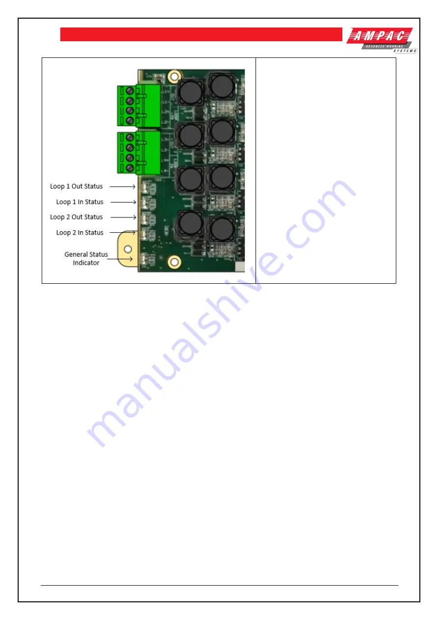
Loop Status Indicators
AMBER: Fault – short, open, overload
RED: power is present
In redundant mode – only the Out port will
be active under normal conditions
General Status Indicator
OFF: cards have no power or processor
is fault
FLASHING GREEN: board is operating,
no faults
FLASHING AMBER: board has a fault
condition
STEADY AMBER: Not receiving
commands from the Distribution CPU
8.9.3 Field wiring - Use of Ferrites on each Loop WIP card
Note:
Two x MIS3019 ferrite core items are packed with each LOOP WIP card (
6350-LILC
). It is necessary
for the installer to connect the ferrites on each loop circuit as shown below
Содержание EvacU Elite
Страница 1: ...EvacU Elite Emergency Warning Intercom System EWIS Install Commission and User Manual MAN3137 2 ...
Страница 5: ...12 Definitions 121 ...
Страница 78: ...Page 71 EVACU ELITE INSTALLATION COMMISSIONING AND USER MANUAL ...
Страница 80: ...Page 73 EVACU ELITE INSTALLATION COMMISSIONING AND USER MANUAL Figure 7 1 24U Cabinet Front and side view ...
Страница 90: ...Page 83 EVACU ELITE INSTALLATION COMMISSIONING AND USER MANUAL Figure 8 2 MIC wiring standard ...
Страница 91: ...Page 84 EVACU ELITE INSTALLATION COMMISSIONING AND USER MANUAL Figure 8 3 MIC wiring voltage reversal ...
Страница 101: ...Page 94 EVACU ELITE INSTALLATION COMMISSIONING AND USER MANUAL 8 7 1 Field wiring Figure 8 6 150Watt amplifier wiring ...
Страница 104: ...Page 97 EVACU ELITE INSTALLATION COMMISSIONING AND USER MANUAL 8 8 3 Field wiring Figure 8 7 Quad radial EIS wiring ...
Страница 107: ...Page 100 EVACU ELITE INSTALLATION COMMISSIONING AND USER MANUAL Figure 8 8 Dual loop EIS wiring ...
Страница 111: ...Page 104 EVACU ELITE INSTALLATION COMMISSIONING AND USER MANUAL Figure 8 10 Network wiring 2 core copper ...
Страница 112: ...Page 105 EVACU ELITE INSTALLATION COMMISSIONING AND USER MANUAL Figure 8 11 Network wiring Single mode single fibre ...
Страница 113: ...Page 106 EVACU ELITE INSTALLATION COMMISSIONING AND USER MANUAL Figure 8 12 Network wiring Single mode dual fibre ...
Страница 114: ...Page 107 EVACU ELITE INSTALLATION COMMISSIONING AND USER MANUAL Figure 8 13 Network wiring Multi mode dual fibre ...
Страница 115: ...Page 108 EVACU ELITE INSTALLATION COMMISSIONING AND USER MANUAL Figure 8 14 Network wiring Mixed Fibre ...
Страница 116: ...Page 109 EVACU ELITE INSTALLATION COMMISSIONING AND USER MANUAL Figure 8 15 Networking wiring Mixed UTP ...
Страница 119: ...Page 112 EVACU ELITE INSTALLATION COMMISSIONING AND USER MANUAL Figure 8 18 Cable routing left hand side ...
Страница 120: ...Page 113 EVACU ELITE INSTALLATION COMMISSIONING AND USER MANUAL Figure 8 19 Cable routing right hand side ...


