

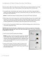


System Power Supply
TURN OFF THE POWER SWITCH BEFORE CHANGING ANY MODULES AND/OR DISCONNECTING ANY CABLES,
OR ELSE THE FUSE WILL BLOW TO PROTECT THE CIRCUITRY.
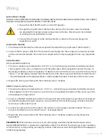
Wiring
1. Ensure that the ON/OFF switch is in the OFF position.
2. Through the top left side of the back box, bring in the AC power wires. Knockouts
are provided for making conduit connections to the box. All wiring is to be installed
according to local and national codes.
3. Connect the AC power to the terminal blocks as shown in the wiring diagram in
Appendices A and F.
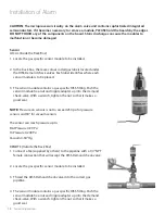
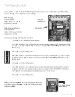
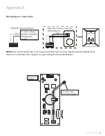
Annunciator Module
1. The Annunciator Module has a female receptacle located at the top right side of the board (J1).
2. Connect the DC power cable from the System Power Supply into the receptacle connection located
on the annunciator module. The connector is keyed and can only be plugged in one way, (Appendix
B).
Sensor Module
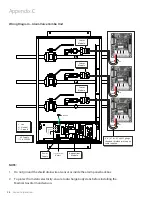
LOCAL (Inside the Back Box)
1. The sensor module is provided with a 6"-8" (0.1 m-0.2 m) #22 gauge stranded, shielded twisted pair
cable supplied. One wire is red (positive) and the other wire is black (negative). Connect the wires to
the display module as shown in Appendix C. Take the red wire from the sensor and attach it to terminal
“” on the display module. Take the black wire from the sensor and attach it to terminal “Sensor
-”. The terminal block on the display module is clearly marked for proper connection of the sensor wires.
2. Repeat the above procedures with the remaining sensor modules.
REMOTE (Outside the Back Box)
1. The sensor module is provided with a 6" - 8" (0.1m - 0.2m) #22 gauge stranded, shielded twisted pair
cable supplied. Connect the wires to a junction box (not supplied) located near the sensor as per the
wiring diagram in Appendix D.
2. Connect a shielded twisted pair cable from the junction box to the back box assembly. Knockouts are
provided throughout the alarm back box. Up to 2,500 feet (750 m) of #22 gauge stranded, shielded
twisted pair cable must be used.
3. Connect the red wire from the cable to the terminal on the display module marked ””.
Connect the black wire to terminal “Sensor -” (see Appendix D).
4. Repeat the above procedures with the remaining sensor modules using the wiring diagram in
Appendix D.
PLEASE NOTE:
When remote sensors are used, a #22 gauge stranded, shielded twisted pair cable is
required (BELDEN #8451 or equivalent, supplied by others). Ensure that the proper gas sensor module is
connected to its corresponding area display module, otherwise an error message (E02) will be displayed
on the Display module.
www.amico.com
11
Содержание Alarm Valve Combo Unit
Страница 1: ...Installation and Maintenance Manual Alarm Valve Combo Unit Alert 1 v1 6...
Страница 31: ......