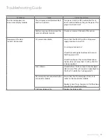
Symptom
Cause
Corrective Action
Gas reading incorrect
Loose connection of DISS fittings
Ensure that the sensor module is properly
connected to the DISS demand check-valve
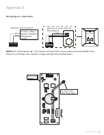
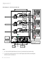
Sensor module is not properly wired to the
display module
Ensure that the sensor module is properly
wired to the display module by using wiring
diagram in Appendix C or D
Defective sensor or requires calibration
Replace the sensor module
The ribbon cable is not properly connected
to the display module
Pull out the ribbon cable and connect
it back in again, while ensuring that it is
seated properly
Defective display module
Replace the display module
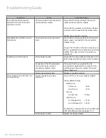
System
Cause
Corrective Action
Page
E01
No sensor is connected or board failure
Connect a sensor and check circuit board
26/27
E02
Sensor and Display Module mismatched.
Ensure that the Sensor and Display Module are for the
same gas
16
E03
The High set-point was set below the Low set-point
or vice versa.
Recalibrate the High and Low setpoint to proper
values
13/14
E04
Incorrect type of Sensor connected
(e.g. 250 psi sensor on a 100 psi range)
Connect the correct Sensor to the matching Display
Module
E06
Cable between the sensor and display module
shorted out or reversed polarity
Reverse polarity or replace cable if defective
26/27
E07
Out of calibration / Sensor not reading gas
Replace the sensor module
26/27
Error Code Messages on the Display Module
Troubleshooting Guide
NOTE:
Any of other error codes, contact Amico technical support to isolate the issue
www.amico.com
19
Содержание Alarm Valve Combo Unit
Страница 1: ...Installation and Maintenance Manual Alarm Valve Combo Unit Alert 1 v1 6...
Страница 31: ......

