background image

Model Numbers

Notes:

•  The power supply requires 1 gang per box.

•  Example: English, 3 valves, 1/2" Oxygen, 3/4" Medical Air and 1-1/4" Medical Vacuum. Will be in a 

4 gang box, not a 3 gang: AVU-1O2A4V

•  The 1-1/2" valve will have an empty space above the valve.

•  Example: a box with a 1/2" Oxygen, 3/4" Medical Air and 1-1/2" Medical Vacuum and a power 

supply will require a 5 gang box not a 4 gang box.

•  The 2" valve will be assembled in a 6-1/2" deep box and shall accommodate up to a maximum of four 

gases. The 2" valve shall be positioned on the bottom of the assembly. The height measurements 

of the 6-1/2" deep valve box are the same as the 3-7/8" deep valve box. When comparing height 

measurements, consider the gap above the 2" valve.

•  Example: a valve box with 1/2" valve, 2" valve and a power supply would be in a 3 gang, 6-1/2" 

deep box, which would be the same height as the 4 gang, 3-7/8" valve box.

•  2-1/2" and 3" valve assemblies are only offered as singles.

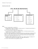
Alarm Valve Combo Unit

AVL-XGXGXGXGXGXGXG

The ”L” Defines the 

Language:

U  =   English (NFPA)
E  =   English (CSA/ISO)
F  =   French (CSA/ISO)
S  =   Spanish (NFPA)

The ”G” Defines the Gas:

O = Oxygen
A  =  Medical Air
V  = MedVac
2  =  Nitrous Oxide
N = Nitrogen
C  =  Carbon Dioxide
W  =  WAGD (NFPA)
E  =  AGSS (ISO)
I  =  Instrument Air

Replace ”X” with the Valve Size:

1  =  1/2" [1.3 cm] 

05

2  =  3/4" [1.9 cm] 

07

3  =  1" [2.5 cm] 

10

4  =  1-1/4" [3.2 cm] 

12

5  =  1-1/2" [3.8 cm] 

15

6  =  2" Full Port [5.1 cm] 

20F

20


Amico Corporation

Содержание Alarm Valve Combo Unit

Страница 1: ...Installation and Maintenance Manual Alarm Valve Combo Unit Alert 1 v1 6...

Страница 2: ...ciator Module 8 Alarm Valve Display Module 8 Sensor Module 8 Installation of Alarm 9 10 Local Sensor Only 9 Standing Pressure Test 9 Frame Module Assembly 9 Sensor 10 Local 10 Remote 10 Wiring 11 Syst...

Страница 3: ...p Switches 16 Troubleshooting Guide 17 19 Table of Error Codes 17 19 Error Code Messages on the Display Module 19 Model Numbers 20 21 Spare Parts Numbers 22 Dimensions 23 Appendix A Wiring Diagram Aut...

Страница 4: ...Corporation or their distributors All alarms should not be repaired or altered without prior written or verbal approval of Amico Corporation or its distributors Failure to comply will void all warran...

Страница 5: ...HI and LOW set points on display module Available in 1 to 7 display modules Built in relay for remote annunciator applications Introduction The Alarm Valve Combo Unit is a 2 in 1 design which combine...

Страница 6: ...ool remove rags 3 Test the system per appropriate standards to ensure that the intended gas and vacuum services are connected to the appropriate lines WARNING Misconnection of the gases could lead to...

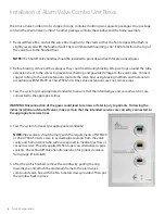
Страница 7: ...lose shutoff valves in the event of fire explosion or damage to the pipeline systems or equipment In Alarm Valve Combo Unit boxes the Shutoff Valve handles become accessible after the window has been...

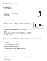
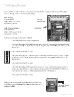
Страница 8: ...Appendix B for connection to another Amico alarm or a building management system Alarm Valve Display Module The module provides a digital display of the actual pressure vacuum of a gas being monitored...

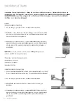
Страница 9: ...the brazing of pipe stubs has been completed the system can be pressure tested Standing Pressure Test Perform a standing pressure test on the piping system as per NFPA 99 Health Care Facilities or CSA...

Страница 10: ...so that it makes a good seal CAUTION The microprocessor circuitry on the alarm valve unit contains sophisticated integrated semiconductors If it becomes necessary to remove a module PLEASE hold the bo...

Страница 11: ...nd attach it to terminal Sensor on the display module Take the black wire from the sensor and attach it to terminal Sensor The terminal block on the display module is clearly marked for proper connect...

Страница 12: ...ensor from Area Module v4 0 P a g e 1 6 FIELD ADJUSTMENTS THE ANNUNCIATOR MODULE NOISE LEVEL CONTROL Factory Default 90 Decibles To decrease noise level 1 Locate jumper at J5 Move jumper to LVL1 90 dB...

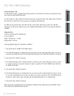
Страница 13: ...desired value 3 Set switch 7 to the OFF position 4 The LED will display LO followed by the current set point Indicating the system is ready to accept a new Low set point Adjust set point using the UP...

Страница 14: ...HI followed by the current set point Indicating the system is ready to accept a new High set point Do not adjust this set point since the High set point is not used 3 Set switch 7 to the OFF position...

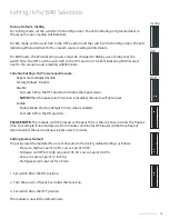
Страница 15: ...the repeat alarm function is disabled the alarm will not repeat Enable Enable Mode Factory Default 30 min when enabled Set switch 5 to the ON position PLEASE NOTE The module with the lowest set Repea...

Страница 16: ...TCH TAMPERING WITH THESE POSITIONS WILL RESULT IN AN ERROR MESSAGE BEING DISPLAYED EO2 AND WILL DISABLE THE ELECTRICAL INTERLOCK FROM THE GAS SPECIFIC SENSOR CHANGES TO THESE SWITCHES SHOULD ONLY BE D...

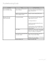
Страница 17: ...h on the power supply module is turned ON AC wiring not connected Check the building electrical breaker to ensure that the power is ON Check the voltage at the terminal block above the transformer Ens...

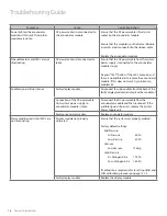
Страница 18: ...le signal will not silence Faulty display module Disconnect the ribbon cable from the back of the faulty display modules and replace the module s Connection of the DC power cable from system power sup...

Страница 19: ...tion Page E01 No sensor is connected or board failure Connect a sensor and check circuit board 26 27 E02 Sensor and Display Module mismatched Ensure that the Sensor and Display Module are for the same...

Страница 20: ...1 2 deep valve box are the same as the 3 7 8 deep valve box When comparing height measurements consider the gap above the 2 valve Example a valve box with 1 2 valve 2 valve and a power supply would be...

Страница 21: ...ALERT 2 SENSOR MODULE USA AIR ENG ALERT 2 SENSOR MODULE USA OXY ENG ALERT 2 SENSOR MODULE USA VAC ENG ALERT 2 SENSOR MODULE USA WAG ENG ALERT 2 SENSOR MODULE USA INSTRUMENT AIR ALERT 2 AVC DISPLAY MO...

Страница 22: ...ARM VALVE COMBO DIVIDER PLATE FOR 3GAS ALARM VALVE COMBO DIVIDER PLATE FOR 4GAS ALARM VALVE COMBO DIVIDER PLATE FOR 5GAS ALARM VALVE COMBO DIVIDER PLATE FOR 6GAS ALARM VALVE COMBO P S COVER FOR ALARM...

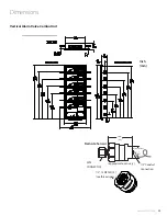
Страница 23: ...Dimensions Vertical Alarm Valve Combo Unit Remote Sensor approximate can vary 1 88 48 Wrench Flats 1 25 DISS CONNECTOR 1 2 Conduit Connection Inch mm 1 2 14 NPSM 13 see thread specs www amico com 23...

Страница 24: ...witched off prior to working on the alarm 2 Risk of electric shock disconnect power at the circuit breaker before removing power supply shield AC Supply 115 to 220 VAC DC Power Cable Connect to Annunc...

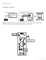
Страница 25: ...ing Diagram Annunciator NOTE Amico recommends max 50 ft to power up buzzer from any Amico devices alarm manifold More than 50 ft a A3P Power V4 is required to supply voltage for the manifold buzzer ww...

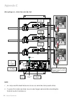
Страница 26: ...y 115 to 220 VAC Power Supply L Live N Neutral G Ground Toggle Switch ON OFF Ground G N L 6 8 0 1 m 0 2 m 22 gauge stranded shielded twisted pair cable supplied Sensor Module Sensor Module Sensor Modu...

Страница 27: ...Alarm and sensors 6 8 0 1m 0 2 m 22 gauge stranded shielded and twisted pair cable supplied Marrette the sensor cable in a junction box supplied by others to the installation cable supplied by others...

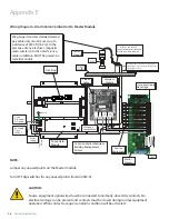
Страница 28: ...C NO HIGH ALARM COM NC NO LOW ALARM AC Supply 115 to 220 VAC Power Supply L Live N Neutral G Ground Toggle Switch ON OFF Ground G N L 6 8 0 1 m 0 2 m 22 gauge stranded shielded twisted pair cable supp...

Страница 29: ...less or other interference cable installation MUST be placed in metallic conduit Signal 30 VDC 1 0 Amps 60 VDC 0 3 Amps 125 VAC 0 5 Amps AVC Display Module to Master Module Distance Maximum 10 000 fee...

Страница 30: ...nnecting sensors or master alarms to source equipment 8 To protect from static electricity ensure to discharge body static before installing the Medical Gas Alarm and Sensors 9 Do not ground the shiel...

Страница 31: ......
Страница 32: ...rporation 85 Fulton Way Richmond Hill ON L4B 2N4 Canada 71 East Industry Court Deer Park NY 11729 USA Toll Free Tel 1 877 462 6426 Tel 905 764 0800 Fax 905 764 0862 Email info amico com www amico com...

Отзывы: