

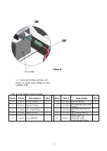

8
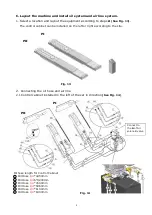
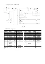
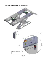
Connect to
the
A
of Air
solenoid valve
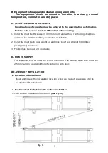
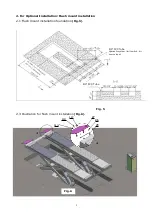
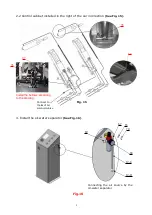
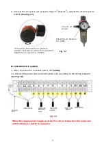
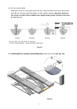
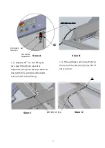
C. Layout the machine and install oil system and air line system.
1. Select a location and layout the equipment according to steps
A
(See Fig. 13)
.
The control cabinet can be installed on the left or right according to the site.
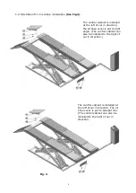
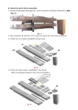
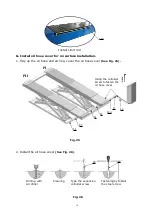
2. Connecting the oil hose and air line
.
2.1
Control cabinet installed in the left of the car in direction
(See Fig. 14)
PII
PI
Fig. 13
Fig. 14
Oil hose length for Control Cabinet
1
Oil Hose
1/4
*4450mm
2
Oil Hose
1/4
6*4200mm
3
Oil Hose
1/4
*4500mm
4
Oil Hose
1/4
*5960mm
5
Oil Hose
1/4
*6100mm
6
Oil Hose
1/4
*6300mm
PI
PII


