background image

DC Asterion Series  

Contents 

M330460-01  Rev A 

xi 

3.6.2


Remote Power Programming by Voltage Source .........................................3-49


3.6.3


Remote Power Programming by 4-20mA Source ........................................3-49


3.7


Remote Overvoltage Programming ........................................................... 3-50


3.8


Remote Output On/Off Control .................................................................. 3-50


3.8.1


Remote Output ON/OFF by Contact Closure ...............................................3-51


3.8.2


Remote Output ON/OFF Control by External Source ..................................3-51


3.9


Parallel and Series Operation .................................................................... 3-52


3.9.1


Parallel Operation .........................................................................................3-52


3.9.2


Series Operation ...........................................................................................3-53


4


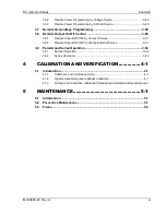
 CALIBRATION AND VERIFICATION ............... 4-1


4.1


Introduction .................................................................................................. 4-1


4.1.1


Calibration and Verification Cycle ................................................................... 4-1


4.1.2


Digital programming and readback calibration ............................................... 4-1


4.1.3


Analog control interface calibration (Standard and Isolated analog interface)4-1


5


 MAINTENANCE ............................................... 5-1


5.1


Introduction .................................................................................................. 5-1


5.2


Preventive Maintenance ............................................................................... 5-1


5.3


Fuses ............................................................................................................. 5-2


Содержание Sorensen Asterion AST Series

Страница 1: ...M330460 01 Rev A www powerandtest com DC Asterion 1U Operation Manual ...

Страница 2: ......

Страница 3: ... respective owners and are used herein for identification purposes only Notice of Copyright M330460 01 DC Asterion 1U Operation Manual 2018 AMETEK Programmable Power Inc All rights reserved Exclusion for Documentation UNLESS SPECIFICALLY AGREED TO IN WRITING AMETEK PROGRAMMABLE POWER INC AMETEK a MAKES NO WARRANTY AS TO THE ACCURACY SUFFICIENCY OR SUITABILITY OF ANY TECHNICAL OR OTHER INFORMATION ...

Страница 4: ... to the instructions of AMETEK is opened modified or disassembled in any way without AMETEK s consent or is used in combination with items articles or materials not authorized by AMETEK The Buyer may not assert any claim that the Products are not in conformity with any warranty until the Buyer has made all payments to AMETEK provided for in the Purchase Order Agreement Product Return Procedure 1 R...

Страница 5: ...nes including those to application and maintenance equipment must be grounded properly for both personnel and equipment safety Always ensure that facility AC mains input is de energized prior to connecting or disconnecting any cable In normal operation from the front panel the operator does not have access to hazardous voltages within the chassis However depending on the application configuration ...

Страница 6: ...llow to cool before servicing DO NOT TOUCH Touching some parts of the instrument without protection or proper tools could result in damage to the part s and or the instrument TECHNICIAN SYMBOL All operations marked with this symbol are to be performed by qualified maintenance personnel only ELECTRICAL GROUND This symbol inside the instrument marks the central safety grounding point for the instrum...

Страница 7: ...nterference when the equipment is operated in a commercial environment This equipment generates uses and can radiate radio frequency energy and if not installed and used in accordance with the instruction manual may cause harmful interference to radio communications Operation of this equipment in a residential area is likely to cause harmful interference in which case the user will be required to ...

Страница 8: ...mpatibility directive European Council directive 2014 30 EU generally referred to as the EMC directive and to the requirements of the Low Voltage directive European Council directive 2014 35 EU 93 68 EEC dated 22 July 1993 In addition these models have been found compliant with FCC 47 CFR Part 15 Subpart B107 e Class A 109 g Class A Since the Low Voltage Directive is to ensure the safety of the eq...

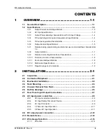
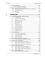
Страница 9: ...igital Interface Characteristics 1 7 1 2 10 Protection Function Characteristics 1 8 1 2 11 Environmental Specifications 1 8 1 2 12 Mechanical Specifications 1 9 1 2 13 Regulatory Agency Compliance 1 9 2 INSTALLATION 2 1 2 1 Inspection 2 1 2 2 Contents of Shipment 2 1 2 3 Mechanical Installation 2 2 2 4 Rack Mounting 2 3 2 5 Chassis Removal from Rack 2 4 2 6 Outline drawings 2 5 2 7 Rear Panel Inpu...

Страница 10: ...gs Screen 3 31 3 1 9 Warning Fault Screen 3 34 3 1 10 Local Remote Screen 3 35 3 1 11 Parallel Series Screen 3 36 3 2 Output Verification 3 36 3 2 1 Constant Voltage Mode Operation 3 36 3 2 2 Constant Current Mode Operation 3 37 3 2 3 Overvoltage Protection 3 38 3 2 4 Constant Power Mode 3 39 3 3 Remote Analog Programming Connector 3 40 3 3 1 Remote Analog Isolated Interface Control Option 3 40 3 ...

Страница 11: ...1 3 8 2 Remote Output ON OFF Control by External Source 3 51 3 9 Parallel and Series Operation 3 52 3 9 1 Parallel Operation 3 52 3 9 2 Series Operation 3 53 4 CALIBRATION AND VERIFICATION 4 1 4 1 Introduction 4 1 4 1 1 Calibration and Verification Cycle 4 1 4 1 2 Digital programming and readback calibration 4 1 4 1 3 Analog control interface calibration Standard and Isolated analog interface 4 1 ...

Страница 12: ...mming and External User Control Interface Connector Type 2 18 Table 2 10 Analog Programming and External User Control Interface Connector Type2 20 Table 2 11 Analog Programming and External User Control Interface Connector Pin out 2 23 Table 2 12 RS 232C Interface Connector Type 2 23 Table 2 13 RS 232C Interface Connector Pinout 2 24 Table 2 14 USB Interface Connector Type 2 24 Table 2 15 USB Inte...

Страница 13: ...ace 8P8C Modular Connector 2 25 Figure 3 1 Splash Screen 3 1 Figure 3 2 Power On Screen Displaying Model Version 3 1 Figure 3 3 Output Enabled Warning Screen 3 2 Figure 3 4 HOME Screen Menu 1 3 2 Figure 3 5 HOME Screen Menu 2 3 2 Figure 3 6 HOME Screen Menu 3 3 2 Figure 3 7 Dashboard Screen in CC CV Mode 3 4 Figure 3 8 Real Time Immediate Output Parameter Adjustment 3 5 Figure 3 9 Touch Screen Num...

Страница 14: ...r Limit 3 18 Figure 3 43 Power User Limit 3 18 Figure 3 44 Analog Reference Mode 3 19 Figure 3 45 Volatge Reference Mode 3 19 Figure 3 46 Current Reference Mode 3 19 Figure 3 47 Power Reference Mode 3 20 Figure 3 48 OVP Reference Mode 3 20 Figure 3 49 Voltage Average Samples 3 20 Figure 3 50 Current Average Samples 3 20 Figure 3 51 User V I Limits Screen 3 21 Figure 3 52 Output Sense Setting Scree...

Страница 15: ...libration 3 33 Figure 3 88 System Settings Screen Default Screen Enabled 3 33 Figure 3 89 System Settings Screen Factory Default 3 34 Figure 3 90 System Settings Screen Parallel Chassis Reset 3 34 Figure 3 91 Fault Screen 3 35 Figure 3 92 OVP Warning Screen 3 35 Figure 3 93 Local Remote Screen 3 35 Figure 3 94 Slave Parallel Screen 3 36 Figure 3 95 Slave Series Screen 3 36 Figure 3 96 Constant Pow...

Страница 16: ...ure 3 109 Remote Output On Off Using Isolated AC or DC Source 3 51 Figure 3 110 Remote Output On Off Using Isolated TTL CMOS Source 3 51 Figure 3 111 Parallel Connection and Remote Sense 3 53 Figure 3 112 Series Connection with Anti Parallel Diodes 3 54 ...

Страница 17: ...itive easy to use front panel touchscreen or the Ethernet LXI USB and RS232 standard control interfaces as well as through the optional GPIB control interface Figure 1 1 Asterion DC Series Power Supply 1U Models The touchscreen function group icons include a Dashboard Output Programming Parameters Measurements Ramp and Triggers Configuration Control Interfaces and System Settings Function selectio...

Страница 18: ...AST XXX AR XXX D X C E X X SERIES Asterion UNIT OUTPUT VOLTAGE VDC 40 60 AUTO RANGE Blank Fixed Range AR Auto Ranging UNIT OUTPUT CURRENT ADC 42 28 85 56 125 83 PRODUCT FAMILY D DC FORM FACTOR U 1 1U UNIT INPUT VOLTAGE VAC C 90 145 VAC 1 ph 180 264 VAC 1 ph 3 ph D 400 V 3 ph 1 E 480 V 3 ph FRONT PANEL E Enhanced GPIB OPTIONS 0 None 1 GPIB ADDITIONAL OPTIONS 0 None 1 Isolated Analog Figure 1 2 Aste...

Страница 19: ...urrent and Voltage Models 1U Models Power 1 7 kW 3 4 kW 5 0 kW Voltage V Current A 40 42 85 125 60 28 56 83 1 2 2 AC input specifications Input Voltage Nominal Rating 1 Phase line neutral Low Input Range 100VAC 132VAC High Input Range 200VAC 240VAC 3 Phase Line Line 200VAC 240VAC Input Voltage Operating Range 1 Phase line neutral 90 145 VAC low input range and 180VAC 264VAC high input range 3 Phas...

Страница 20: ...1 7 kW 3 4kW 3 4 kW 5 0 kW 1 2 4 DC output programming and measurement specifications PROGRAMMING READBACK FRONT PANEL OR REMOTE DIGITAL INTERFACE Voltage Output programming accuracy 0 1 of rated output voltage Current Output programming accuracy 0 2 of rated output current Power Output programming accuracy 0 3 of rated output power Overvoltage programming accuracy 1 maximum of rated output voltag...

Страница 21: ... of programming change from rated output voltage to zero with rated resistive load Current fall time is same as the voltage fall time 7 maximum time from 100 0 of programming change from rated output voltage to zero with No load 8 Typical time to recover within 0 75 of rated output voltage for load step change of 90 of rated output current 9 RMS ripple noise over 20 Hz to 300 kHz bandwidth is meas...

Страница 22: ...Full Scale range 0 V to 10 V corresponds to 0 100 full scale output Minimum recommended Load 100 kΩ typical Maximum Load 20 kΩ Monitor accuracy 1 of full scale output Remote ON OFF Control input for Output ON OFF Switch Relay contact closure or direct short circuit from this terminal to signal return will enable turn on the output of the supply Remote circuit must sink up to 3 mA from 5 VDC to ena...

Страница 23: ...us 1 V User fed voltage can be of maximum 30 V Current Maximum 0 5 A Auxiliary power output Two Auxiliary power outputs of 15 V and 5 V These auxiliary power outputs can be controlled from the power supply or by giving appropriate signals on the digital input enable pins provided for the same Maximum current for the Auxiliary power output 1 A 12 Unit is rated for 1 Accuracy at 5V 10V for Voltage P...

Страница 24: ...n reaching limit In CV mode on reaching current or power limits results in shutdown of output In CC mode on reaching voltage or power limits results in shutdown of output In CP mode on reaching voltage or current limits results in shutdown of output In CV or CC or CP mode shutdown delay on reaching the limit is programmable from 100 ms to 5 s AC Input Overcurrent Protection Internal fuses in each ...

Страница 25: ...provisions for mounting rack slides slides and flange brackets handles options available Cooling Force air cooling linear variable fan speed control air intake at front sides and exhaust at rear Acoustic Noise 68 dBA maximum measured at 1 m with A weighting 1 2 13 Regulatory Agency Compliance Parameter Specification EMC CE marked for EMC Directive 2014 30 EV per EN61326 1 2013 Class A for emission...

Страница 26: ......

Страница 27: ...AMETEK Customer Service Department at 858 458 0223 local or 1 800 733 5427 toll free in North America 2 2 Contents of Shipment Depending on the model configuration and options selected for your Asterion Series power source the ship kit may include additional parts and accessories Minimum items included in the ship kit P N 5330339 01R 1 AMETEK CD ROM P N M550008 01 containing the Asterion DC Series...

Страница 28: ...it in parallel series with another 2 3 Mechanical Installation The Asterion DC Series power source is designed for rackmount applications there is an option for a rack mounted slide Rack mounting requires installing the flange brackets with handles to the side of the chassis using M4 0 7 x 6 mm Philips flat head screws to mount the brackets to the chassis and 8 32 Philips flat head screws to mount...

Страница 29: ...acent to the unit there is no need for additional clearance above or below the source It should be supported in the rack using appropriate L brackets or rackmount slides Refer to Figure 2 1 for typical rackmount installation Recommended rackmount kits are as follows 1 Rackmount Slide Kit Option AMETEK part number 5330201 01R 2 Rackmount Flange Bracket Kit Option AMETEK part number 5330241 01R Inst...

Страница 30: ...k at full extension To disconnect and remove the chassis from the rack depress the flat steel spring located on the slides inward and pull the chassis forward To return the chassis back into the rack from full extension depress the flat steel spring located on the slides inward and push the chassis back When the chassis is at full extension the flat springs are located behind the front rack rails ...

Страница 31: ... Asterion DC Series power source Figure 2 3 shows the rear panel view of the power source and locations of the rear panel connectors Figure 2 4 shows the protective covers installation for the AC input and DC output Item A as shown in Figure 2 4 using M4 0 7 KEPS nuts with a maximum tightening torque of 1 1 Nm 10 lb in The components comprising the covers are supplied in the ship kit ...

Страница 32: ...Overview DC Asterion Series 2 6 M330460 01 Rev A Figure 2 2 Installation Drawing Enhanced front panel version 1U Models ...

Страница 33: ...IB option Figure 2 4 Rear Panel Protective Cover Installation 2 7 Rear Panel Input Output Connections Figure 2 3 for the rear panel view of the 1U model power source showing the location of the connectors Table 2 1 provides details of the connectors located in the rear panel of the power source ...

Страница 34: ...l to the AC mains ground CAUTION Under no condition should the negative output terminal exceed 600V to earth ground Floating the negative output terminal subjects the internal control circuitry of the power supply to the same potential as present at the negative output terminal In a unit with the standard Non Isolated Analog Interface the signals of 44 pin analog programming and external user inte...

Страница 35: ...the specifications of Section 1 2 for AC input current requirements and derating of output power as a function of AC input voltage 2 8 1 AC input overcurrent protection The Asterion DC Series power source has fuses at the AC input for fault protection These fuses are internal to the chassis and are not user accessible They provide fault isolation in case a failure occurs of internal components or ...

Страница 36: ...C INPUT L2 AC Input 90 264 VAC Line 2 input from utility AC mains For 1 Phase input connect lines to terminals L1 and L2 or L2 and L3 or L1 and L3 AC INPUT L3 AC Input 90 264 VAC Line 3 input from utility AC mains For 1 Phase input connect lines to terminals L1 and L2 or L2 and L3 or L1 and L3 GND Safety Ground N A Safety Ground connection from utility earth protection ground Table 2 2 AC Input Co...

Страница 37: ...t have a voltage that does not exceed 264 VAC Use wires with ratings equal to or greater than the current rating listed in the specification Section 1 2 2 A ground wire must be connected from the rear panel safety ground terminal or the rear panel safety ground stud to the utility power earth protection ground 2 8 5 3 Phase AC Input Operation Connect the utility AC source wires to the rear panel A...

Страница 38: ... Power Supply Type Connection Description 1 7 kW to 5 kW 40V 60V models Bus bars with holes for M8 bolts on each terminal POS and NEG Table 2 4 DC Output Power Connections Manufacturer Low Current High Current Panduit P PV or PN series or equivalent Standard stranded wire LCA Series or equivalent Flexible stranded wire LCAX Series or equivalent Note Contact lug manufacturer for recommended crimpin...

Страница 39: ...ocal or remote corresponding sense signal is used by the controller as the voltage feedback Figure 2 7 shows the remote sense connector at the rear panel of the power supply Remote sensing is used to compensate for the voltage drop that occurs across the wires connecting the load to the output of the power source A separate pair of wires is routed to measure the voltage at the terminals of the loa...

Страница 40: ...Connection at the Load 60V 40V Model 2 11 Wire Gauge Selection Care must be taken to properly size all conductors for the input and output of the power source This section provides guidance in the selection of wire size CAUTION Use wire with Class B or C stranding Fine stranded flexible wire should not be used unless crimp on lugs or ferrules are utilized that are approved for fine stranded cables...

Страница 41: ...cable specification for your power applications the same engineering rules apply whether at the input or output of an electrical device Therefore this guide applies equally to the input cable and output cable for this power source and application loads Power cables must be able to safely carry maximum load current without overheating or causing insulation degradation It is important to power sourc...

Страница 42: ...lication and thus the expected performance Table 2 8 presents wire resistance and resulting cable voltage drop at maximum rated current with the wire at 20 C Copper wire has a temperature coefficient of α 0 00393Ω C at t1 20 C so that at an elevated temperature t2 the resistance would be R2 R1 1 α t2 t1 The output power cables must be large enough to prevent the line voltage drop total of both out...

Страница 43: ...or stored energy is present such as a battery a second blocking diode in series with the output is recommended to protect the power supply Refer to Figure 2 9 2 12 1 1 BLOCKING AND ANTI PARALLEL DIODES Ensure that the chosen components are suitably rated for the inductance and energy to be dissipated The Peak Reverse Voltage ratings should be a minimum of 2 times the Power Supply maximum output vo...

Страница 44: ...044 102L001 or equivalent Table 2 9 Analog Programming and External User Control Interface Connector Type Function Characteristics Remote Analog Programming of Output Voltage Current and Power Independent Signal inputs for output voltage current and power programming using External Analog Reference Analog reference source is user selectable and can be a voltage resistance or 4 20 mA source Selecte...

Страница 45: ... high provides external hardware triggering of voltage and current ramp functions Signal connects to Open anode of opto isolator diode with internal 1kΩ series resistor internal to power supply Voltage Rating Maximum 24 V Minimum 5V Low state 0 3 V max High State 2 7 V min TRIGGER OUT Output signal active low synchronization pulse of 10 ms when a change in the output occurs There is an Option to f...

Страница 46: ...olated Proper connection should be made to signal returns with respect to input programming equipment Improper connection might result in ground return loops and as a result internal power supply damage might occur output current could then flow by way of the external connection to the return pins 12 18 22 28 29 36 40 and 41 Refer to Table 2 11 for pin details 44 Pin Conn Ametek P N 856 044 00 Pin...

Страница 47: ...les high output on pin 37 Up to 24V capable 3V max low 2 7V min high 12 RTN DIGITAL GND Return for Pin 7 8 9 10 11 12 13 ESTOP DIGITAL IN Short to Pin 14 to permit operation Internally tied to 5V through a 2 49k resistor 14 RTN DIGITAL GND Return for Pin 13 ESTOP 15 RTN_UPWR POWER GND Return for Pin 30 USER_PWR 16 RTN_HV ISO GND Return for Pin 1 ON OFF_HV and Pin31 ON OFF_ISO 17 18 RTN_PRG ANALOG ...

Страница 48: ...an connect between 5V to 24V to control digital output relay output voltage If left unconnected digital and relay outputs have 4 5V high states 31 ON OFF_ISO DIGITAL IN Isolated remote control input for output on off with a logic signal a logic high 3 3V to 24V signal will enable turn on the output of the supply and a logic low signal disables turns off the output This control input is optically i...

Страница 49: ... for use by the user 1A max current 44 AUX15_EN DIGITAL IN Apply a high to enable output on pin 42 15V_AUX Up to 24V capable 0 3V max low 2 7V min high Table 2 11 Analog Programming and External User Control Interface Connector Pin out With the option Remote Isolated Analog Interface control the control signal return is isolated from the output power negative terminal 2 13 2 RS 232C Serial Interfa...

Страница 50: ... 12 for view of connector Table 2 14 for the connector type and Table 2 15 for pin descriptions A standard USB cable between the Asterion Series power source and a computer should be used For EMC considerations a ferrite core can be added to the cable Ametek P N 991 642 28 Manufacturer P N CS28B0642 CAUTION Connecting the power source to the computer controller through an USB hub is not recommende...

Страница 51: ...ries Programming Manual P N M330461 01 distributed on the CD M550008 01 For EMC considerations a ferrite core can be added to the cable Ametek P N 991 642 28 Manufacturer P N CS28B0642 Figure 2 13 LAN Interface 8P8C Modular Connector Connector Type LAN Interface Standard RJ45 connector Table 2 16 USB Interface Connector Type Pin Ethernet Signal EIA TIA 568A EIA TIA 568B Crossover 1 Transmit Receiv...

Страница 52: ...6 M330460 01 Rev A Pin Ethernet Signal EIA TIA 568A EIA TIA 568B Crossover 8 Transmit Receive Data 3 Brown with white stripe or solid brown Brown with white stripe or solid brown Table 2 17 LAN Interface 8P8C Modular Connector Pinout ...

Страница 53: ...DC Asterion Series Overview M330460 01 Rev A 2 27 This page intentionally left blank ...

Страница 54: ......

Страница 55: ...ly the Dashboard screen Refer to Figure 3 7 Figure 3 1 Splash Screen Figure 3 2 Power On Screen Displaying Model Version If output is enabled in Power ON Settings PONS screen refer to Figure 3 32 and supply is in Local mode a warning screen is shown Refer to Figure 3 3 before the Dashboard Screen It warns the user that the output will be enabled at the end of 10 second countdown The process can be...

Страница 56: ...he HOME screen Each menu of a screen could be selected by tapping its associated selection field box through the touch screen or by selecting it with the rotary encoder and depressing clicking the rotary encoder SELECT switch Refer to Figure 3 4 Figure 3 5 Figure 3 6 and Table 3 1 Figure 3 4 HOME Screen Menu 1 Figure 3 5 HOME Screen Menu 2 Figure 3 6 HOME Screen Menu 3 ...

Страница 57: ...Constant Power Mode Regulation Mode Output state and OVP MEASUREMENTS Provides measurement of output parameters Voltage Current and Power CONFIGURATION Provides setup of Power ON States PONS User V I limit Total System Current Profiles Regulation mode and Measurement Settings CONTROL INTERFACE Provides setup of remote digital interfaces RS232 GPIB LAN and Analog SYSTEM SETTINGS Provides display of...

Страница 58: ...tting is possible using the rotary encoder CURRENT Programs the output current in amps Real time setting is possible using the rotary encoder POWER Programs the power in constant power mode for power regulation in KW Real time setting is possible using the rotary encoder NOTE The unit will operate in Constant Power Mode if power limit is set Measure VOLTAGE Displays the floating point value of the...

Страница 59: ...ctive tapping the selection field selects it Afterwards the keypad screen will be displayed Tapping numerical value keys the decimal point key or the polarity key selects them while the back arrow key erases the last entry To enter a negative value first enter the number then the minus sign The selected values appear in the upper left parameter window and the cursor moves to the next available pos...

Страница 60: ...one of two ways 1 Tapping the OUTPUT PROGRAM screen on Home Screen 1 of the front panel touch screen 2 Scrolling to the OUTPUT PROGRAM screen with the encoder and depressing the encoder switch The UP arrow button will return to the previously selected screen menu in this case the HOME Screen 1 The HOME button will return to the home screen that has the top level menu for the sub menu being display...

Страница 61: ... the model refer to Figure 3 13 Figure 3 13 Current Setting OVP Programs the Overvoltage Protection OVP threshold for the output voltage Exceeding the OVP threshold will result in shutdown of the output and the output voltage programmed to zero refer to Figure 3 14 Figure 3 14 OVP Setting REGULATION Selects options for regulation of the output voltage CC CV CP Constant Power Constant Voltage and C...

Страница 62: ...ay settings to ON or OFF state refer to Figure 3 17 Figure 3 17 Output State Setting 3 1 5 Measurements Screen The Measurements the floating point value of the DC Output Voltage Output Current and Output Power the DC Output Voltage Output Current and Output Power The Measurements screen is shown in refer to Figure 3 18 Refer to Section 3 1 2 1 for navigating to Measurements Screen Figure 3 18 Meas...

Страница 63: ...RAMP The Voltage Ramp menu allows to configure and execute voltage ramp refer to Figure 3 20 The Voltage Ramp menu allows the selection of parameters such as Volt To Volt Curr Time and Trigger Figure 3 20 Voltage Ramp Screen The Voltage Ramp menu has the following fields Entry Description Volt Sets the start voltage for the ramp To Volt Sets the end voltage for the ramp Curr Sets the Current limit...

Страница 64: ...tton will only be enabled after Initialize button is pressed Refer to Figure 3 22 Figure 3 22 Voltage Ramp Screen SW Trigger Waiting for Trig This field is displayed after Initialize button is pressed in HW trigger Mode refer to Figure 3 23 This shows that the supply is waiting for an active high pulse of 10ms on the MOLEX connector pin 8 TRIGGER_IN and pin 12 DIN_RTN to generate the Voltage Ramp ...

Страница 65: ... to 10s Select the Trigger mode as SW software Click on Initialize Click on Trigger Ramp Observe that Trigger Ramp button will change to Abort button Observe the voltage ramp signal using oscilloscope Clicking on the Abort button will abort the ramp Clicking on the Exit button will exit the Voltage Ramp screen Example 2 Creating a Voltage ramp using Hardware Trigger mode Set the Volt to 25V Set th...

Страница 66: ...urrent for the ramp To Curr Sets the end current for the ramp Volt Sets the volt limit for the ramp Time Sets the time in seconds to reach from start current to end current Trigger Sets the trigger mode for the ramp In SW Software trigger mode the ramp is generated as soon as the Trigger Ramp button is pressed In HW Hardware trigger mode the ramp will be generated when an active high pulse of 10ms...

Страница 67: ...Designations and Functionsfor PIN details Figure 3 27 Current Ramp Screen HW Trigger Abort In SW trigger mode when Trigger Ramp button is pressed it changes to Abort button In HW trigger mode when external trigger is received Waiting for Trig will change to Abort button refer to Figure 3 28 Pressing the Abort button aborts the ramp Figure 3 28 Current Ramp Screen Abort Exit Exits the Current Ramp ...

Страница 68: ...et the Volt to 25V Set the Time to 10s Connect an appropriate load to the supply Select the Trigger mode as HW Hardware Click on Initialize Observe that Trigger Ramp button will change to Waiting for Trig Give an external trigger i e an active high pulse of 10ms on the MOLEX connector pin 8 TRIGGER_IN and pin 12 DIN_RTN to generate the Current Ramp Observe that Waiting for Trig will change to Abor...

Страница 69: ...ption will be disabled on single chassis operation refer to Figure 3 30 This option will be enabled when two or more chassis are connected refer to Figure 3 31 For multiple chassis connection and operation refer to section 3 9 fo Figure 3 30 Multi Chassis Screen Single Chassis Figure 3 31 Multi Chassis Screen Multiple Chassis 3 1 7 2 POWER ON SETTINGS PONS The PONS Menu allows user to set the Powe...

Страница 70: ...Power ON Settings Menu Screen 2 Figure 3 34 Power ON Settings Menu Screen 3 The Power ON Settings menu has the following fields Entry Description Voltage Sets the power on default voltage refer to Figure 3 35 Figure 3 35 Power On Voltage Setting Current Sets the power on default current refer to Figure 3 36 ...

Страница 71: ...Figure 3 37 Power On Output Setting Regulation Mode Sets the power on default value of the Regulation Mode refer to Figure 3 38 Figure 3 38 Regulation Mode OVP Sets the power on default value of the Over Voltage Protection refer to Figure 3 39 Figure 3 39 Power On OVP Setting Output Sense The Output Sense menu allows user to set the output voltage sense of the unit to either Internal or External r...

Страница 72: ...e 3 40 Output Sense Setting Screen Voltage User Limit Sets the power on default value of the voltage User limit refer to Figure 3 41 Figure 3 41 Voltage User Limit Current User Limit Sets the power on default value of the Current User Limit refer to Figure 3 42 Figure 3 42 Current User Limit Power User Limit Sets the power on default value of the Power User Limit refer to Figure 3 43 Figure 3 43 P...

Страница 73: ...xternal Ref Source is selected as 4 20mA FSC will not be applicable Figure 3 45 Volatge Reference Mode Curr Ref Mode Sets the power on default value of the Current Reference Mode refer to Figure 3 46 When external Ref Source is selected as Resistive FSC Full Scale unit will change to k Ohms When external Ref Source is selected as 4 20mA FSC will not be applicable Figure 3 46 Current Reference Mode...

Страница 74: ...esistive and 4 20mA source is not applicable to external OVP programming Figure 3 48 OVP Reference Mode Voltage Average Sets the power on default value of the voltage average Samples samples refer to Figure 3 49 Figure 3 49 Voltage Average Samples Current Average Sets the power on default value of the current average Samples samples refer to Figure 3 50 Figure 3 50 Current Average Samples ...

Страница 75: ...oad against damaging voltages currents and or power levels The User V I Limits menu has the following fields Entry Description Voltage Sets the upper user limit on the programmed output voltage Current Sets the upper user limit on the programmed output current Power Sets the upper user limit on the programmed output power 3 1 7 4 OUTPUT SENSE The Output Sense menu allows user to set the output vol...

Страница 76: ...tage readback Allows to set a value between 1 to 5 The value of 1 factory default provides the fastest response time in the readings but less rejection of noise Curr Avg Samples Sets the number of current readings to average together to reduce noise in the current readback Allows to set a value between 1 to 9 The value of 1 factory default provides the fastest response time in the readings but les...

Страница 77: ...ol through the data communications interfaces From control Interface screen user can also configure Analog Programming feature to program the power supply parameters from external sources such as voltage Resistance and 4 20mA The top level menu of the Control Interface screen is shown in Figure 3 55 Refer to Section 3 1 2 1 for navigating to Control Interface Screen Figure 3 55 Control Interface S...

Страница 78: ...en Figure 3 57 RS232 Setting Screen 3 1 8 2 LAN Entry Description LAN Configures the LAN Ethernet communications interface refer to Figure 3 58 Figure 3 58 LAN Screen LAN SETTINGS Lists the configuration settings of the LAN interface Refer to Figure 3 59 Figure 3 59 LAN Screen Settings ...

Страница 79: ...Figure 3 61 NOTE When DHCP is selected the IP address is assigned by the network DHCP server If DHCP server fails to assign an IP address and Auto IP is enabled the unit gets an IP address in the range of 169 254 X X Figure 3 61 LAN Screen DHCP Auto IP Enables or disable the Auto IP configuration when DHCP is ON Refer to Figure 3 62 Figure 3 62 LAN Screen Auto IP Host Name Allows setting a unique ...

Страница 80: ... 3 64 Figure 3 64 LAN Screen Port IP Address Sets the static IP address for the unit Refer to Figure 3 65 Figure 3 65 LAN Screen IP Address Subnet Mask Sets the subnet mask for use in static IP configuration Refer to Figure 3 66 Figure 3 66 LAN Screen Subnet Mask Gateway Address Sets the gateway address for use in static IP configuration Refer to Figure 3 67 ...

Страница 81: ...en Restore Default is pressed a confirmation window will pop up After user confirmation LAN settings will be set to factory Default Refer to Figure 3 68 Figure 3 68 LAN Screen Restore Default Apply Now Applies the LAN settings to the supply Refer to Figure 3 69 Figure 3 69 LAN Screen Apply 3 1 8 3 ANALOG Entry Description Analog Configures the Analog programming interface refer to Figure 3 70 ...

Страница 82: ... Refer Figure 3 71 and Figure 3 72 Figure 3 71 Analog Mode Settings 1 Figure 3 72 Analog Mode Settings Screen 2 Configure Sets parameter values and controls operation of the Analog Analog mode Programming interface refer to Figure 3 73 Figure 3 73 Configure Analog Mode Screen Analog Ref Configures the Analog Programming Reference Source Refer to Source Figure 3 74 ...

Страница 83: ...Resistive FSC Full Scale unit will change to k Ohms When external Ref Source is selected as 4 20mA FSC will not be applicable Figure 3 75 Voltage Reference Mode Screen Current Ref Mode Configures the Current Reference Mode refer to Figure 3 76 When Current reference mode is selected as External the Current setting field in Dashboard screen will be disabled and Current setting field in Dashboard wi...

Страница 84: ...eld in Dashboard will display equivalent power setting from external program source NOTE When Analog Ref Source is selected as Resistive FSC Full Scale unit will change to k Ohms When external Ref Source is selected as 4 20mA FSC will not be applicable Figure 3 77 Power Reference Mode Screen OVP Ref Mode Configures the Over Voltage Protection Reference Mode refer to Figure 3 78 NOTE Resistive and ...

Страница 85: ...ure Figure 3 79 Refer to Section 3 1 2 1 for navigating to System Settings Screen Figure 3 79 System Settings Screen Top Level Menu 1 Figure 3 80 System Settings Screen Top Level Menu 2 The following menus are available in the System Settings Screen top level menu Firmware Version Hardware Limits Language LCD Brightness Default Screen and Factory Default Entry Description System Status Displays th...

Страница 86: ...s the language of the display menus German English Spanish French Russian Japanese Chinese or Korean Refer to Figure 3 84 Figure 3 84 System Settings Screen Language LCD Brightness Sets the brightness of the LCD backlight as a percentage of the maximum that is available the default setting is 70 Tapping on the Right or Left arrow buttons or selecting them with the encoder and clicking the encoder ...

Страница 87: ...gs Calibration Default Screen Selects whether the Default screen showing measured voltage current and power is enabled or disabled refer to Figure 3 88 It allows to set the time out if the default screen is enabled Timeout Interval Selects the time in seconds for how long Dashboard screen must be inactive before the Default screen is displayed Figure 3 88 System Settings Screen Default Screen Enab...

Страница 88: ...e Parallel Chassis connection Refer to Figure 3 90 Chassis Reset Figure 3 90 System Settings Screen Parallel Chassis Reset 3 1 9 Warning Fault Screen The following warning Fault screen may appear during operation Refer to Figure 3 91 Pressing on View Faults will display all the Fault Warning description with an option to clear the Fault These warnings indicate description of Faults which has occur...

Страница 89: ...the display press Clear Fault button Refer to Figure 3 92 The display will return to Home Screen Menu and the output will remain disabled Note It is important to correct the condition that caused the OVP prior to re enabling the output 3 1 10 Local Remote Screen This screen is displayed when operation is controlled by computer Pressing Set Local from Local Remote screen returns the supply to Local...

Страница 90: ...ther through the front panel or by the remote analog voltage programming input To verify operation in Constant Voltage mode follow these steps 1 Ensure that there is no load connected to the output 2 Ensure that the remote sense is connected to the output terminals 3 Connect a digital voltmeter DVM across the rear panel positive and negative output terminals observing the correct polarity Make sur...

Страница 91: ...he setup and perform the check again If the function continues to fail contact the factory for assistance 3 2 2 Constant Current Mode Operation In Constant Current mode operation the output current is regulated at the selected value while the output voltage varies with the load requirements The current could be programmed either through the front panel or by the remote analog current programming i...

Страница 92: ...operation did not function as indicated above verify the setup and perform the check again If the function continues to fail contact the factory for assistance 3 2 3 Overvoltage Protection The Overvoltage Protection OVP function allows the supply to shut down the output if it were to exceed a preset voltage This may be used to protect sensitive circuits or loads from damage caused by an excessive ...

Страница 93: ...tting as appropriate for the application If OVP is not used then OVP programming may be set at maximum approximately 110 of the rated output voltage of the supply 11 If OVP mode did not function as indicated above verify the setup and perform the check again If the function continues to fail contact the factory for assistance 3 2 4 Constant Power Mode The Constant Power Mode allows the supply to r...

Страница 94: ...24 is at the same potential as the negative output terminal of the power supply not isolated Proper connection should be made to signal returns with respect to input programming equipment Improper connection might result in ground return loops and as a result internal power supply damage might occur output current could then flow by way of the external connection to the J1 common J1 6 and J1 24 Re...

Страница 95: ...sistance connected to signal return Pin 18 0 5 kΩ or 0 10kΩ 0 100 of full scale output voltage 4 VPRG_VSOUR VPRG_4 20mA_SOUR ANALOG IN Remote control input for voltage programming using a voltage source 0 5 VDC or 0 10 VDC 0 100 of full scale output voltage Do not exceed an input of 12 VDC Signal return is Pin 18 5 OVPPRG_VSOUR ANALOG IN Remote control input for overvoltage programming using a vol...

Страница 96: ... optically isolated from the output power negative terminal of the power supply up to 500 VDC 19 IPRG_VSOUR IPRG_4 20mA_SOUR ANALOG IN Remote control input for current programming using a voltage source 0 5 VDC or 0 10 VDC 0 100 of full scale output current Do not exceed an input of 12 VDC Signal return is Pin 18 20 IPRG_ISOUR ANALOG OUT Current source of 1 mA for remote current programming using ...

Страница 97: ... the output power negative terminal of the power supply up to 500 VDC Signal return is Pin 16 RTN_HV 32 33 PPRG_VSOUR PPRG_4 20mA_SOUR ANALOG IN Remote control input for power programming using a voltage source 0 5 VDC or 0 10 VDC 0 100 of full scale output power Do not exceed an input of 12 VDC Signal return is Pin 18 34 PPROG_ISOUR ANALOG OUT Current source of 1 mA for remote power programming u...

Страница 98: ...ce may be used as a programming device When using remote current programming a shielded twisted pair cable is recommended to prevent noise interference to programming signals 3 4 1 Remote Current Programming by Resistance Analog Reference source is selected as Resistance from the front Panel Refer to Figure 3 98 The resistance programming default coefficient for output current is 100 rated output ...

Страница 99: ...age value can be modified to any voltage between 2V to 10V from front panel screen refer to Section 3 1 8 3 Default FSC voltage value is 10V where 10V corresponds to 100 output current The corresponding voltage programming coefficients for output current are 100 rated output current FSC VDC This produces transfer functions for output current as follows Iout Vdc 100 rated output current 10 VDC with...

Страница 100: ...programming configuration is used for applications that require the output voltage be programmed controlled from a remote instrument An external resistance or external voltage source or 4 20mA source may be used as a programming device When using remote voltage programming a shielded twisted pair cable is recommended to prevent noise interference to programming signals 3 5 1 Remote Voltage Program...

Страница 101: ...RTN_PRG and Analog Reference source is selected as Voltage from the front Panel Refer to Figure 3 102 The Full Scale voltage value can be modified to any voltage between 2V to 10V from front panel screen refer to Section 3 1 8 3 Default FSC voltage value is 10V where 10V corresponds to 100 output voltage The corresponding voltage programming coefficients for output voltage are 100 rated output vol...

Страница 102: ...rom a remote instrument An external resistance or external voltage source or 4 20mA source may be used as a programming device When using remote voltage programming a shielded twisted pair cable is recommended to prevent noise interference to programming signals 3 6 1 Remote Power Programming by Resistance Analog Reference source is selected as Resistance from the front Panel Refer to Figure 3 104...

Страница 103: ...1 8 3 Default FSC voltage value is 10V where 10V corresponds to 100 output power The corresponding voltage programming coefficients for output power are 100 rated output power FSC VDC This produces transfer functions for output power as follows Pout Vdc 100 rated output power 10 VDC with Vdc in volts or Pout Vdc 100 rated output power FSC VDC with Vdc in volts 0 10VDC VOLTAGE Source 33 18 PPRG_VSO...

Страница 104: ...ly between Pins 5 OVPRG_VSOUR and Pin 18 RTN_PRG to set the output overvoltage trip level A 0 10 VDC signal equals 0 110 of rated output voltage See Figure 3 107 for connection requirements This full scale programming voltage source range can be set to any value between 2V to 10VDC from front panel Refer to Section 3 1 8 3 0 10VDC VOLTAGE Source 5 18 OVPRG_VSOUR Figure 3 107 Remote Overvoltage Pro...

Страница 105: ... Off Control by Contact Closure 3 8 2 Remote Output ON OFF Control by External Source Application of AC DC voltage between Pins 1 and 16 or TTL CMOS voltage between Pins 31 and 16 will turn on the power supply this interface is opto isolated from circuit common See Figure 3 109 and Figure 3 110 for connection requirements AC or DC Source 1 16 ON OFF_HV Figure 3 109 Remote Output On Off Using Isola...

Страница 106: ... supply Slave 1 use another interface cable to connect the PAR OUT connector to the PAR IN connector of the third power supply Slave 2 Continue these interconnections up to a maximum of 5 power supplies Repeat connection between Slave 1 CAN OUT and Slave 2 CAN IN 4 Connect the Positive output terminals of all the power supplies and the load 5 Connect the Negative output terminals of all the power ...

Страница 107: ...ge available is the sum of the maximum voltages of each supply Each supply displays its own output voltage and the load voltage is the sum of each front panel display CAUTION Under no condition should the negative output terminal of any power supply exceed 600 V to chassis earth ground This is limited by the isolation and creepage clearance distances internal to the power supply construction If a ...

Страница 108: ...lel diode power diode capable of the maximum current of the series group connected across the output but reverse biased is recommended to protect against sinking current into a supply should one supply be ON while another other is OFF as shown in Figure 3 112 4 Diode D2 shown in the figure is optional if the load has stored energy such as a battery Refer to Section 2 12 Figure 3 112 Series Connect...

Страница 109: ...DC Asterion Series Overview M330460 01 Rev A 3 55 This page intentionally left blank ...

Страница 110: ......

Страница 111: ...alibrate only as needed 4 1 2 Digital programming and readback calibration Refer to the DC Asterion programming manual for calibration of display readback and remote digital programming 4 1 3 Analog control interface calibration Standard and Isolated analog interface The analog control interface calibration requires opening of the chassis top cover and it should be carried out by service personnel...

Страница 112: ......

Страница 113: ...touch any circuits and or terminals that are energized 5 2 Preventive Maintenance WARNING The OFF position of the front panel power switch does not remove AC input from internal circuits or input terminal blocks Disconnect external AC input before servicing unit CAUTION For safe and continued operation of the DC Asterion Series always operate the unit in a temperature and humidity controlled indoo...

Страница 114: ...ue If there is any evidence of short circuits or arcing overheating or corrosion contact the factory for recommended service 5 3 Fuses There are no user replaceable components in the power supply Internal fuses are listed in Table 5 1 Fuses are sized for fault isolation and an open fuse might indicate that a circuit component has been damaged Contact the factory for further assistance CAUTION To r...

Страница 115: ...I IEEE 488 Option 1 8 Input Frequency nominal rating 1 3 range 1 3 Input Overcurrent Protection 2 8 Circuit Breaker Fuse Rating 2 8 Input Voltage nominal rating 1 3 operating range 1 3 Input Output Connections Input Overcurrent Protection 2 8 Safety Disconnect Device 2 8 Safety Ground Wire 2 8 Inrush Current 1 3 Inspection 2 26 Installation 1 9 INSTALLATION 2 1 Isolation Voltage 1 4 L LAN 1 7 LAN ...

Страница 116: ...midity 1 8 Remote Current Programming Resistance Control 3 44 Voltage Source Control 3 45 3 48 3 50 Remote Digital Control IEEE 488 option 1 8 LAN 1 7 RS 232C 1 8 USB 1 7 Remote Isolated Analog Interface Control 3 40 Remote Output On Off Control 3 50 Contact Closure Control 3 51 External Source Control 3 51 Remote Overvoltage Protection Programming 3 50 Remote Voltage Programming 3 46 3 48 Resista...

Страница 117: ...DC Asterion Series Index M330460 01 Rev A 3 ...

Страница 118: ...Maintenance DC Asterion Series 4 M330460 01 Rev A This page intentionally left blank ...

Отзывы: