Page 14
Signal Processor
User Guide
LMG GS
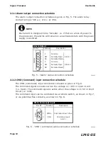
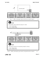
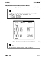
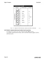
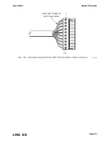
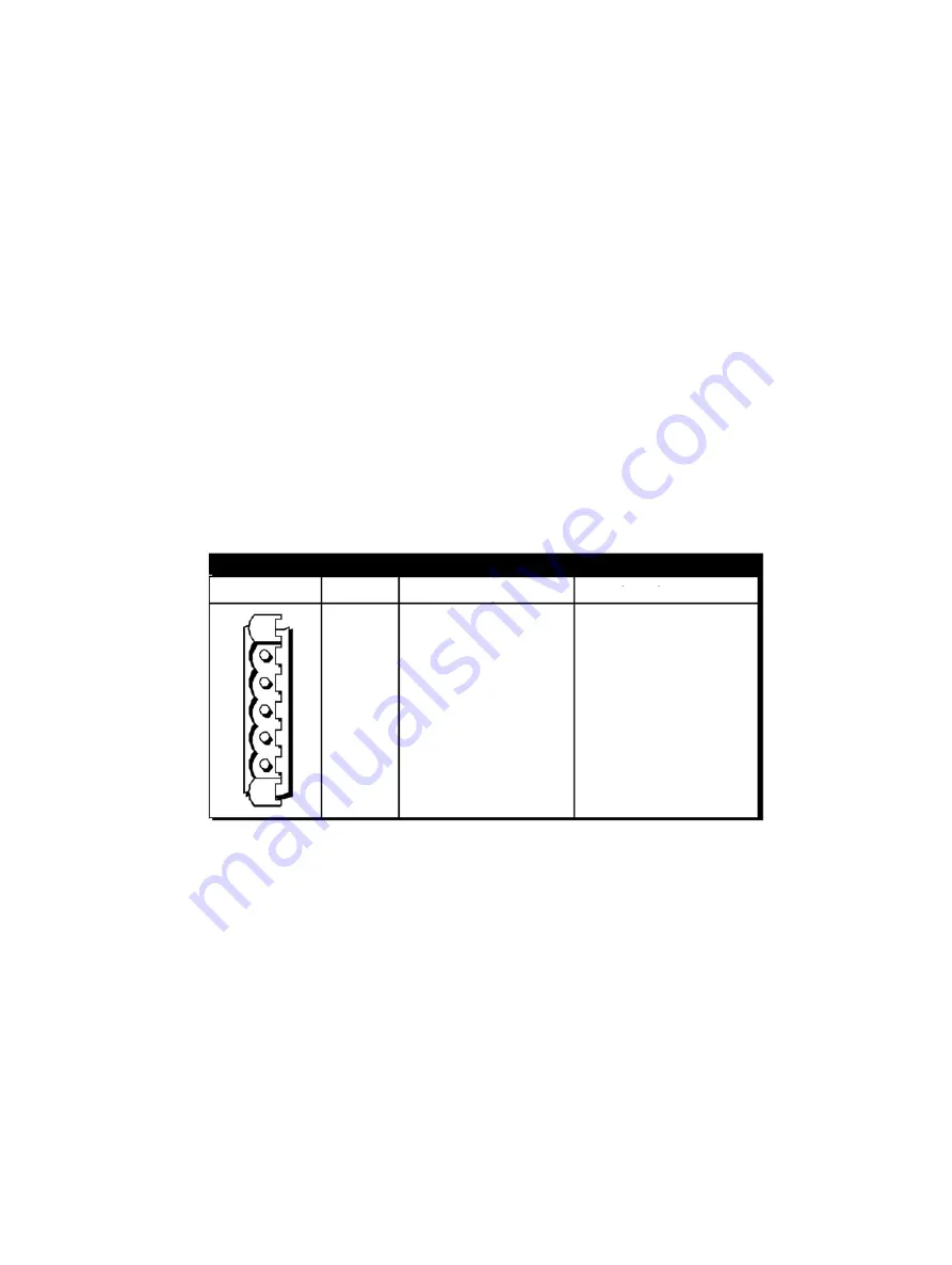
Fig. 9a - System 4 thermometer retransmission output
cable connection schedule
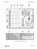
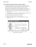
2.2.3 Output (Retransmission output) connection schedule
The output (retransmission output) connection schedule for System 4
thermometers is given in Fig. 9a and the output (retransmission output)
connection schedule for the GST thermometer is given in Fig. 9b.
The processor is supplied fitted for ‘up scale’ operation. The mode of
operation is set by means of a link on the input/output (I/O) board. To gain
access to the link, the back panel of the processor must be removed.
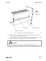
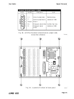
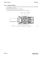
(i) Refer to Fig. 10, unscrew the four screws (A) on the back panel of
the processor.
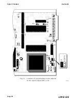
(ii) Slide the I/O board out of the rear of the processor. The location of the
‘up scale/down scale’ selector link is shown in Fig. 11.
(iii) Set the link to the required mode of operation.
(iv) Slide the I/O board into it’s slot in the processor.
(v) Tighten the four screws (A) on the back panel of the processor
(Refer to Fig. 10).
238009a
Pin Nº
Output (Retransmission output)
I +
I -
Screen
V +
V -
1
2
3
4
5
Maximum loop
resistance: 500Ω
Minimum load
resistance: 10kΩ
(Not available on GST I/O
cards)
Current output drive
Current output return
Screen
Voltage output drive
Voltage output return
O
U
TP
U
T
Function
Load
Description
Содержание Land LMG GS
Страница 2: ......
Страница 6: ......
Страница 8: ......
Страница 12: ...Page 4 Signal Processor User Guide LMG GS...
Страница 35: ...Page 27 User Guide Signal Processor LMG GS Fig 20 Access code display 238020...
Страница 62: ......


