Page 12
Signal Processor
User Guide
LMG GS
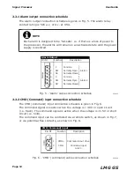
2.2.1 Alarm output connection schedule
The alarm output connection schedule is given in Fig. 5. The alarm relay
contact rating is 50V a.c. or d.c. at 0.5A.
2.2.2 CMD (Command) input connection schedule
The CMD (Command) input connection schedule is given in Fig. 6.
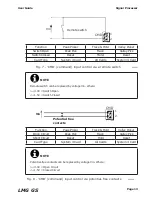
The command signal is inactive when the voltage is >3.0V or open circuit
(i.e. track). The command signal is active when the voltage is <1.5V or short
circuit (i.e. hold).
The command input can be controlled via a remote switch, as shown in Fig.7,
or via potential-free contacts, as shown in Fig. 8.
NOTE
Each alarm is designed to be ‘fail-safe’. i.e. if there is a loss of power to
the processor, the alarms will remain in an activated state until the power
supply is restored.
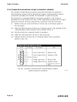
Fig. 5 - ‘Alarm’ cable connection schedule
238005
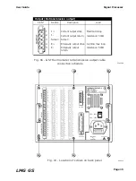
Fig. 6 - ‘CMD’ (command) cable connection schedule
238006
Pin Nº
Alarm Output
CMD (Command) input
C
NO
NC
C
NO
NC
1
2
3
4
5
6
Common
Normally Open
Normally Closed
Common
Normally Open
Normally Closed
Al
ar
m
s
Function
Description
Alarm 1
Alarm 2
Pin Nº
Function
Description
CMD+
1
Command input drive
Command input
return
CMD-
2
CMD
Fig. 8 - ‘CMD’ (command) input control via potential-free contacts
238008
Содержание Land LMG GS
Страница 2: ......
Страница 6: ......
Страница 8: ......
Страница 12: ...Page 4 Signal Processor User Guide LMG GS...
Страница 35: ...Page 27 User Guide Signal Processor LMG GS Fig 20 Access code display 238020...
Страница 62: ......


