background image

L-Series and FCS-18- Graphical User Interface User Manual 


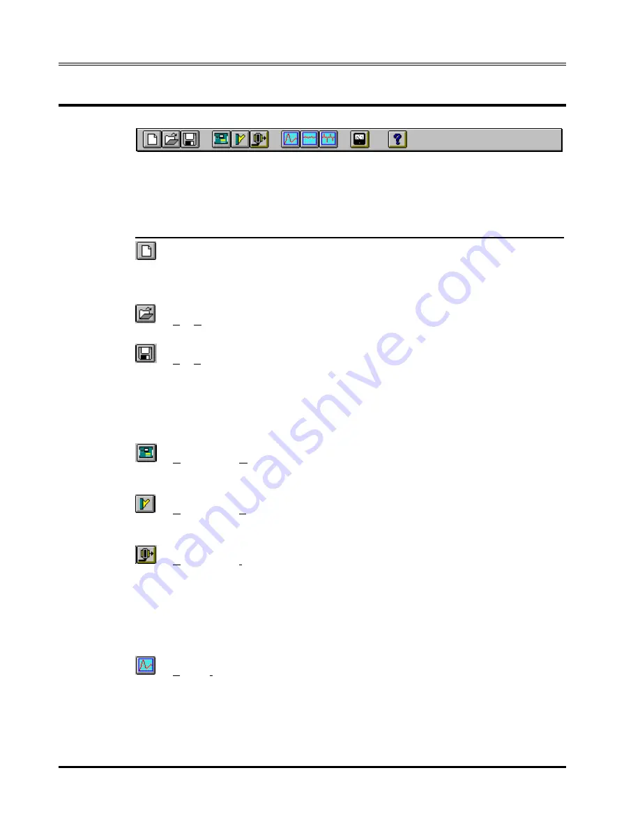
4.7  Using the Toolbar 


The toolbar provides a convenient shortcut for mouse savvy operators. 
Clicking on each of the toolbars icons will cause the corresponding menu and 
sub-menu to be selected at once. The following toolbar icons and their 
corresponding menu equivalents are provided : 

Icon Menu 

equivalent 

Description 


File-New 

Resets all setup information to default values. If 
an actual L-Series is connected to the PC, 
hardware configuration data remains 
unchanged. 


File-Open... 

Opens the File Open dialog box. User can select 
setup file to load. 


File-Save 

Save present settings to disk setup file. If no 
setup was loaded previously, the File Save As... 
dialog box will appear prompting the user for a 
name to save the setup under. If a setup file was 
opened previously, the new settings will be used 
to overwrite the same setup file. To avoid this, 
use the File Save As... menu instead. 


Configuration-Model 

Allows different L series models to be selected 
for simulation purposes. Model can only be 
changed when in simulation mode. 


Configuration-System Settings... 

Shows installed options and hardware 
configuration. Also provides access to output 
and measurement calibration screens. 


Configuration-IEEE Interface... 

Opens the IEEE interface setting and command 
line screen. This screen can be used to change 
the IEEE address used to communicate with the 
L-Series AC source. An interactive command 
line is provided as well to allow the user to send 
IEEE commands directly to the instrument. All L-
Series APE commands are available from a drop 
down list. 


Source-Initialization... 

Opens the initial settings window. This window is 
used to inspect and change the initial power up 
settings. 


30 

California Instruments 

Rev D – March 2011 

Содержание 12000L

Страница 1: ...formation Telephone 800 733 5427 toll free in North America 858 450 0085 direct Fax 858 458 026 Email Domestic Sales domorders sd ametek com International Sales intlorders sd ametek com Customer Service service ppd ametek com Web www programmablepower com March 2011 Document No 4009 969 Rev D ...

Страница 2: ......

Страница 3: ......

Страница 4: ......

Страница 5: ... Copyright L Series and FCS 18 AC Power Source Graphical User Interface Software User Manual 2010 AMETEK Programmable Power Inc All rights reserved Exclusion for Documentation UNLESS SPECIFICALLY AGREED TO IN WRITING AMETEK PROGRAMMABLE POWER INC AMETEK a MAKES NO WARRANTY AS TO THE ACCURACY SUFFICIENCY OR SUITABILITY OF ANY TECHNICAL OR OTHER INFORMATION PROVIDED IN ITS MANUALS OR OTHER DOCUMENTA...

Страница 6: ...ii This page intentionally left blank ...

Страница 7: ...onnel and equipment safety Always ensure that facility AC input power is de energized prior to connecting or disconnecting any cable In normal operation the operator does not have access to hazardous voltages within the chassis However depending on the user s application configuration HIGH VOLTAGES HAZARDOUS TO HUMAN SAFETY may be normally generated on the output terminals The customer user must e...

Страница 8: ...structions of AMETEK is opened modified or disassembled in any way without AMETEK s consent or is used in combination with items articles or materials not authorized by AMETEK The Buyer may not assert any claim that the Products are not in conformity with any warranty until the Buyer has made all payments to AMETEK provided for in the Purchase Order Agreement PRODUCT RETURN PROCEDURE 1 Request a R...

Страница 9: ...nu items with the mouse 29 4 6 Selecting menu items using the keyboard 29 4 7 Using the Toolbar 30 4 8 Status bar 32 4 9 Modal and Non Modal windows 32 5 L Series Hardware Configuration 33 5 1 Model Number and Controller type selection screen 34 5 2 System Settings screen 35 5 3 IEEE Interface screen 36 6 Source control 37 6 1 Source Initialization 38 6 2 Steady State control 39 6 3 Steady state e...

Страница 10: ...Measurement modes 69 8 3 Stay on top feature 70 8 4 Data logging 71 8 4 1 Selecting a data file 71 8 4 2 Selecting the File Mode 72 8 4 3 Selecting the time stamp format 72 8 4 4 Data file comments 73 8 4 5 Data File Format 73 8 5 Using a spreadsheet program 75 8 6 Dynamic data exchange 76 9 Applications 77 9 1 MIL STD 704 77 9 2 RTCA DO 160 78 10 Calibration 79 10 1 Calibration support features 7...

Страница 11: ...rface problems 102 13 2 1 Wrong IEEE address 102 13 2 2 Incompatible IEEE card 103 13 2 3 Card not at specified I O address 104 13 3 Constant or Frequent Syntax Error messages 104 13 4 Configuration errors 104 13 5 Parameter conflicts 105 13 6 Problems not listed 105 13 7 Problem report forms 106 14 Index 109 ...

Страница 12: ...L Series and FCS 18 Graphical User Interface User Manual 8 California Instruments Rev D March 2011 This page intentionally left blank ...

Страница 13: ...erview of the program s operation It also lists details on file formats and other details that may be needed in order to use this program successfully Extensive information can also be found in the on line help supplied with the program Use the Help menu or press on any of the many Help keys located in all program windows for an explanation of the relevant screen or function As always California I...

Страница 14: ... to this manual will be provided in the form of a readme txt file on the distribution disk As such you will not normally receive an new manual when you receive a new software version Major changes to the functionality or operation of this software may require a new manual version as well In this case the integer version number part will be increased and a new manual version will be issued If the L...

Страница 15: ...C IIA or PC AT TNT IEEE interface card Other vendor IEEE interface cards are not supported unless they are compatible at the DLL level2 IEEE Cable Note that the LSGUI can be run in the absence of an L Series power source If no AC source is available or a suitable IEEE controller card cannot be found the LSGUI can be operated in a simulation mode The program will detect these conditions and start u...

Страница 16: ...ert the LSGUI disk in drive A or B If you do not have a 3 5 inch drive on the PC you can copy the contents of the disk to a 5 25 inch diskette on a PC that is equipped with both drive types 3 From the Program Manager select the File Menu 4 From the File Menu select Run 5 At the prompt type A SETUP or B SETUP depending on the drive designator of the drive in which you inserted the disk The setup pr...

Страница 17: ... are copied to the application directory The application directory name is chosen by the user at the time of installation In this manual the default application directory name LSGUI is used path and filename size in bytes date lsgui lsgui exe 216438 9 15 95 lsgui lsgui hlp 62601 9 13 95 Windows system directory files The following support files are copied to the windows system directory path and f...

Страница 18: ...lly you may attempt to manually install the files listed in section 3 3 All files on the distribution diskette are compressed so they cannot be copied directly to the hard disk Instead use the expand exe program that is located in the DOS directory of your PC The correct syntax to use is expand r a source destination The directory path for the destination files should be specified as part of the d...

Страница 19: ... will be informed of software updates and bug fixes that may be released from time to time Please mail the completed end user registration form to the following address California Instruments Corporation Attn Customer Satisfaction Department 9689 Towne Centre Drive San Diego CA 92121 U S A You can also fax a copy of the form to the fax number listed below 858 677 0940 Please specify Customer Satis...

Страница 20: ...L Series and FCS 18 Graphical User Interface User Manual 16 California Instruments Rev D March 2011 This page intentionally left blank ...

Страница 21: ..._________________________ Mailstop __________ City _________________________ State ______ Zip _______ Phone ____ ____________________ Fax ____ _____________________ Software revision Program L Series Graphical user interface Version _________ Rel Date ___ ___ 19___ Company use only Date received Receipt acknowledgment sent yes no Updated version sent ___ ___ 19___ Processed by _____________ CI SWR...

Страница 22: ...L Series and FCS 18 Graphical User Interface User Manual 18 California Instruments Rev D March 2011 This page intentionally left blank ...

Страница 23: ...e LSGUI Use the mouse to double click on the LSGUI icon If you are not comfortable double clicking with a mouse you can also click on the icon once to select it and then press the Enter key The program will load and display the main program window screen Rev D March 2011 California Instruments 19 4 2 First Save Configuration Data Before continuing on with this program be sure to save your L Series...

Страница 24: ...low the main menu bar is the toolbar or buttonbar The toolbar provides mouse click shortcuts for the most commonly accessed menus and sub menus The toolbar can be made invisible from the options menu if screen real estate is small or the user does not like using the mouse Below the menu and toolbar is the main program screen area Here information on the L Series power source that was detected on t...

Страница 25: ...nd in the relevant chapters that follow Figure 2 provides a flowchart of all available menus and sub menus in the LSGUI program Main menu File Configuration Source Options Measurements Applications Help New Open Save Save As Exit Model System Settings IEEE Interface Initialization Steady State Transients Show Data File Show Toolbar Save Configuration File Restore Configuration File MIL STD 704 RTC...

Страница 26: ...ox User can select setup file to load Save Save present settings to disk setup file If no setup was loaded previously the File Save As dialog box will appear prompting the user for a name to save the setup under If a setup file was opened previously the new settings will be used to overwrite the same setup file To avoid this use the File Save As menu instead Save As Save present settings to disk s...

Страница 27: ...tware is printed on the original distribution disk Make sure you keep this information in a secure place and provide the password only to qualified personnel The following three sub menus are available from the Configuration menu Submenu Purpose Model Opens the model selection dialog box This dialog box allows different L series models to be selected for simulation purposes The L Series Model can ...

Страница 28: ...e range can be set from the Initialization window Changes made to this window will be sent to the L Series when the OK button is clicked Steady State Opens the Steady State window This is the virtual front panel or soft front panel of the L Series This window is non modal and can be left open at all times while the LSGUI program is running Transients Opens the Transients windows This modal window ...

Страница 29: ...times The measurement window provides constant readouts of up to 19 parameters Different screen colors are used to indicate different phases Data File Opens a dialog box that allows the user to select a data file for recording of measurement data If no file is selected from this sub menu and data logging is enabled data will be written to the default data file called LS_GUI CSV The default file mo...

Страница 30: ...s visible No check mark indicates the toolbar is not visible Save Configuration File Opens a dialog box which allows the user to save the present hardware configuration data for the connected L Series unit to a disk file The serial number of the unit needs to be specified and will be used as the file name Saving configuration data may be important in case a loss of non volatile memory is ever expe...

Страница 31: ...this sub menu opens a dialog box which enables the user to select all or a subset of MIL STD 704 test programs Program execution can be started from this sub menu as well RTCA DO 160 When available this sub menu opens a dialog box which enables the user to select all or a subset of RTCA DO 160 test programs Program execution can be started from this sub menu as well Note If the L Series unit conne...

Страница 32: ...rch dialog mode Use this sub menu to look for help on a specific topic Index Opens the LSGUI help file at the index page The index page lists all key words and provides jumps to the relevant help topic that covers the concept How to use Help Opens the generic windows Help file on the How to Use Help page If the user is not familiar with the Windows help engine this topic may be appropriate About O...

Страница 33: ...any menu item using the mouse move the mouse pointer to the desired entry and press the left mouse button Click 4 6 Selecting menu items using the keyboard To select any menu using the keyboard hold down the ALT key and press the letter of the menu item that is underlined Thus to select the File menu item hold down the ALT key and press the letter F ...

Страница 34: ...r If a setup file was opened previously the new settings will be used to overwrite the same setup file To avoid this use the File Save As menu instead Configuration Model Allows different L series models to be selected for simulation purposes Model can only be changed when in simulation mode Configuration System Settings Shows installed options and hardware configuration Also provides access to ou...

Страница 35: ...idden behind other windows Source Transients Opens the Transient programming screen This screen allows the 16 transient registers to be programmed and executed Measurements Show Displays the measurement window The measurement window is non modal and can be left open at all times The state of this window opened or closed is reflected by the icon on the toolbar If the icon is depressed the window is...

Страница 36: ...g modal and non modal windows is intended for users not familiar with Windows 3 1 Modal windows are those that when opened cause other tasks to be suspended Thus program operation cannot continue until the user closes the modal window that is presently open The focus will remain on a modal window as long as the program that opened the modal window is running Closing modal windows is commonly done ...

Страница 37: ...es and FCS 18 Graphical User Interface User Manual 5 L Series Hardware Configuration This chapter reviews the operation of the three available configuration screens Rev D March 2011 California Instruments 33 ...

Страница 38: ... to the active model number and controller type When in simulation mode changes made to the selected model number and controller type will take effect when the button is clicked 34 California Instruments Rev D March 2011 To cancel any changes made click on the button instead For help on this screen click on the button If changes are made while an L Series unit is connected and the user clicks on t...

Страница 39: ...igurations are based on the actual L Series unit found at the specified IEEE address The calibration password entry field can be used by qualified calibration personnel to access the output calibration and measurement calibration screens When the correct password is entered here and the ENTER key is pressed the and the buttons will be enabled Refer to Chapter 10 which covers Calibration for detail...

Страница 40: ... mode If a power source is found at the specified IEEE address the program selects normal mode of operation If the power source is set to a different IEEE address or is otherwise not found at the specified IEEE address the simulation mode is automatically selected 3 To interact with the connected L Series unit directly over the IEEE bus The command line and response window can be used to issue Abb...

Страница 41: ...trument control normally associated with instrument front panels There are three source control screens that each affect a different area of operation of the L Series AC source With the exception of the Steady State screen the Source control windows are modal meaning only one of them can be opened at a time and they must be closed before moving to another menu or window ...

Страница 42: ... initialization values are retained in non volatile memory The source initialization screen can be used to inspect the active initialization values and if needed make modifications Modifications made are downloaded to the L Series and saved in non volatile memory as soon as the button is clicked To close this window without affecting any changes use the instead Note that any changes made to the in...

Страница 43: ...mall yellow control shown at the bottom of the windows desktop Rev D March 2011 California Instruments 39 Iconized minimized Steady State control panel The steady state control panel can also be resized using the mouse to consume less screen space Use the standard windows drag handles or select Size from the control box menu Note however that this window cannot be sized larger than its default siz...

Страница 44: ...he desired values and then update the L Series steady state all at once 40 California Instruments Rev D March 2011 6 3 2 Immediate mode If the control panel is in Immediate mode changes made to any of the controls immediately affect the setting of the connected L Series unit This allows the user to slew values up or down using the mouse This mode of operation more closely reflects the operation of...

Страница 45: ...e value to change in intermediate size steps It provides a balance between adjustment speed and accuracy 3 Small step changes Clicking on the left or right arrow This method provides the most precise control but it can be slow when the value needs to be changed to a much higher or lower value This method is best used to make final adjustments 6 4 1 Voltage derating for low frequencies Rev D March ...

Страница 46: ... for all phases to be set to zero volts 6 5 1 Current limit adjustment The maximum amount of current available will be limited when switching to the high voltage range When the high range is selected it may be necessary to trim the current limit value back to avoid exceeding the maximum available current in the high voltage range This is done automatically by the LSGUI program Thus the user may se...

Страница 47: ...anging phase mode will cause the output voltage for all phases to be set to zero volt 6 6 1 Current limit adjustment The maximum amount of current available will be limited when switching to three phase mode When three phase mode is selected it may be necessary to trim the current limit value back to avoid exceeding the maximum available current This is done automatically by the LSGUI program Thus...

Страница 48: ...alifornia Instruments Rev D March 2011 When the steady state control panel is opened the status of the output relay is reflected in this area 6 8 Current limit delay If the connected L Series unit is equipped with a PT type controller the current limit delay control will be available This control allows the current limit trip delay to be programmed Allowable values range from 0 to 1 second in 10 m...

Страница 49: ...it phase B is always disabled 6 9 1 Voltage control Voltage for each phase can be set using a left right slider control The operation of the slider control is similar to that of the frequency control See paragraph 6 4 Voltage is limited on the low end to zero volts On the high end the maximum voltage is determined by the hardware configuration of the connected L Series unit and the currently selec...

Страница 50: ...selection Based on the connected L Series configuration different types of waveforms can be selected for each of three phases The relevant controls will be available to the user if the waveform options are supported by the connected L Series unit Specifically the following configurations are required to support the different waveforms Sine Supported by all L Series AC sources Clipped Only availabl...

Страница 51: ...rbances found on power lines The L Series AC sources are equipped with sixteen non volatile transient memory registers The transient programming screen is used to specify transient types and parameters for each register Once downloaded transients can be executed starting from any of the sixteen registers The ability to link memory registers at random allows for complex sequences and loops to be ea...

Страница 52: ...wn field that lists all available transient types More details on the various transient types will follow Goto V Initial voltage value For transients that affect voltage this value will take effect as soon as the register is recalled For voltage sweeps the Goto V value reflects the start value For voltage drops this field is disabled as a voltage drop always drops the voltage to zero volt at the s...

Страница 53: ... specified in the Delay field Whether it represents a sag or a surge will depend on the steady state frequency present at the time the transient is executed Final F Final frequency value This is the frequency present at the end of the transient delay For frequency steps this field is disabled since the Final F would be identical to the Goto F value anyway Start ø Start angle of transient execution...

Страница 54: ...nce transient registers can be programmed and saved for later use it is possible that the voltage values used in transient step are within limits if the L Series is in high voltage range In low voltage range however the same transient parameters are invalid as they exceed to maximum voltage in the low range No check is made on the present range setting Goto V and Final V values are only limited by...

Страница 55: ...available transient types are no Type Abbreviation 1 Empty Empty 2 Voltage dropout V Drop 3 Voltage step V Step 4 Voltage surge sag V Srg Sag 5 Voltage sweep V Sweep 6 Frequency step F Step 7 Frequency surge sag F Srg Sag 8 Frequency sweep F Sweep 9 Voltage and Frequency sweep VF Sweep 10 Delay Delay The empty type is clearly not an actual transient but merely a place holder No transient data is d...

Страница 56: ...from 1 ms to 9999 seconds At the end of the dropout the output value is set to the value specified by the Final V field 52 California Instruments Rev D March 2011 The illustration shown here reflects an example of a typical V Dropout transient The required row in the data entry screen for this transient would be as shown below In this case register 0 was used to store the transient information Vol...

Страница 57: ...fically useful if the step transient is part of a list of linked registers In this case the delay value will determine how long the value remains at the Goto V value before the link is made to the next register in the sequence At that time whatever transient is in this register may change the voltage to a new value Rev D March 2011 California Instruments 53 The illustration shown here reflects an ...

Страница 58: ...ut value will still be set to the value specified by the Final V field Note that if the Final V value is set to the same value as the Goto V value the V Srg Sag transient effectively becomes a V Step transient The illustration shown here reflects an example of a typical V Srg Sag transient The required row in the data entry screen for this transient would be as shown below In this case register 0 ...

Страница 59: ...value specified by the Final V field Note that if the Final V value is set to the same value as the Goto V value the V Sweep transient effectively becomes a V Step transient The illustration shown here reflects an example of a typical V Sweep transient The required row in the data entry screen for this transient would be as shown below In this case register 0 was used to store the transient inform...

Страница 60: ...d The delay value can range from 1 ms to 9999 seconds At the end of the delay period the output frequency will remain at the Goto F value so there is no need to specify a Final V value 56 California Instruments Rev D March 2011 The illustration shown here reflects an example of a typical F Step transient The required row in the data entry screen for this transient would be as shown below In this c...

Страница 61: ...e end of the delay period the output value will still be set to the value specified by the Final V field Note that if the Final F value is set to the same value as the Goto F value the F Srg Sag transient effectively becomes a F Step transient Rev D March 2011 California Instruments 57 The illustration shown here reflects an example of a typical F Sag transient The required row in the data entry s...

Страница 62: ...ut frequency will remain at the value specified by the Final F field Note that if the Final F value is set to the same value as the Goto F value the F Sweep transient effectively becomes a F Step transient The illustration shown here reflects an example of a typical F Sweep transient The required row in the data entry screen for this transient would be as shown below In this case register 0 was us...

Страница 63: ... voltage and frequency sweeps The illustration shown here reflects an example of a typical VF Sweep transient The required row in the data entry screen for this transient would be as shown below In this case register 0 was used to store the transient information This transient can be used for many different types of combined transients by judicious use of the Goto and Final values 45 V rms 70 ms 1...

Страница 64: ...on For example entering 1 will cause the field to be reset Empty Link fields indicate no link is made to another register WARNING Linking registers will cause a slight delay when switching from one transient register to the next This delay is approximately 3 msec when the Link to register contains a single parameter transient or 4 msec when the Link to register contains a VFSweep transient This de...

Страница 65: ...t to single phase these controls will be disabled and only phase A will have a check mark For three phase units or units with the phase mode option set to three phase these controls can be set by the user Rev D March 2011 California Instruments 61 When transient data is downloaded the status of these phase check marks is incorporated in the generation of the register program statements sent to the...

Страница 66: ...er This is especially true for errors in the link field see section 7 3 If the LSGUI is in simulation mode transfer to the instrument can not be achieved Instead a window listing all program statements that would be sent to a real unit is displayed This can be a useful feature when troubleshootin g transient programs or when the user wants to analyze the actual step and delay values generated by t...

Страница 67: ...ram file name Any eight character name can be used If an existing transient program file is selected its contents will be overwritten with the active data from the transient entry screen If a new name is entered the transient data will be saved under the new file name 7 6 2 Retrieving transient list When the button is clicked a file dialog box appears listing all available transient lists on disk ...

Страница 68: ...ptive name such as EMPTY TLS Anytime the data present needs to be erased load the EMPTY LST file Alternatively the button located in the bottom right corner can be used When this button is clicked the user will be asked for a confirmation before all entries are erased Press No to abort the erase operation If Yes is selected all entries will be erased You may want to store the list information to d...

Страница 69: ...an be time consuming it is important not to accidentally loose information when the Transient window is closed To prevent this from happening the LSGUI program will automatically save the contents of all the parameter fields any time the button is clicked The data is stored to a default file called LSGUI DTL in the program directory Any time the Transient screen is opened the LSGUI looks for the p...

Страница 70: ...number before pressing the button If this register is linked to other registers execution will proceed according to the link sequence Refer to section 7 3 The button can be used to stop transients in progress This may not always work immediately and an error message may pop up indicating the attempt to stop the transient in progress was unsuccessful Clicking the button several times usually resolv...

Страница 71: ... measurements that are available from the L Series Measurements can be displayed on screen and stored to disk The ability to use the LSGUI program as a DDE server is also discussed Examples are provided for using collected data in spreadsheet programs such as Excel Rev D March 2011 California Instruments 67 ...

Страница 72: ...r a three phase system with MODE option in single phase mode phase B and phase C will be disabled If all check marks are removed only the frequency will be measured Frequency measurements are always enabled and cannot be turned off Measurements that are disabled will retain their most recent value but will be dimmed to indicate that they are no longer updated It is possible to enable and disable m...

Страница 73: ... This mode will cause all measurements to be taken once when the button is clicked Once a cycle has been started it will run through completely even if the button is clicked This is to avoid incomplete measurement records when the data logging function is enabled Cycle mode In this mode of operation measurements are taken continuously This mode of operation is required for data logging application...

Страница 74: ...working in other windows programs the stay on top feature can be useful as it allows you to switch to other Windows programs without loosing sight of your measurements To reduce the amount of space needed on screen you may elect to resize the measurement window to a smaller size You will not be able to size the window to a larger size than the default as there is no other information to be display...

Страница 75: ... between recordings 8 4 1 Selecting a data file The data is stored in a comma separated value ASCII text file using the path and filename shown at the bottom of the Measurement window There may not be enough room to display the entire path as indicated by leading dots Data logging filenames can be set using the Measurements Data File sub menu Selecting this menu displays a dialog box that allows t...

Страница 76: ...le record entry is automatically time stamped with the date and time the data was obtained from the L Series unit The time serial number format is practical when the data is to be analyzed or displayed using a spreadsheet program such as Excel as this format is identical to that used by Excel for tracking dates and times To display a time serial number in readable form use the Cell format data tim...

Страница 77: ...e record Each record consists of the following fields Field name Description Timestamp Date and time of recording for this record Frequency Frequency value Volt A Voltage rms for phase A Current A Current rms for phase A Phase A Phase angle with respect to phase A Power A Real power for phase A Appt Power A Apparent power for phase A Power Factor A Power factor for phase A Volt B Voltage rms for p...

Страница 78: ... and therefore do not show 1995 08 24 15 30 27 User Comment line goes here Time_serial F V A I A A W A VA A PF A 34935 64615 60 0 125 2 0 21 0 00 28 26 1 000 34935 64620 60 0 125 2 0 30 0 00 28 38 1 000 34935 64626 60 0 125 2 0 21 0 00 27 26 1 000 34935 64633 60 0 125 2 0 30 0 00 28 38 1 000 34935 64639 60 0 125 2 0 30 0 00 28 38 1 000 34935 64645 60 0 125 2 0 30 0 00 28 38 1 000 34935 64650 60 0 ...

Страница 79: ...red in individual columns with each row representing one measurement cycle Once imported into Excel analysis and graphical trend data displays are easily generated Refer to your Excel documentation for details The example below illustrates the data sample shown in section 8 4 5 as it appears when loaded in an Excel spreadsheet Column A set to Date_Time format Other spreadsheets programs such as Lo...

Страница 80: ...ld be used to access DDE data from the LSGUI program Application Name lsgui Topic Name measurement Item Names ampa Voltage amplitude phase A cura Current phase A pwra Real power phase A appa Apparent power phase A phsa phase angle phase A with respect to phase A pwfa power factor phase A ampb Voltage amplitude phase B curb Current phase B pwrb Real power phase B appb Apparent power phase B phsb ph...

Страница 81: ... tests designed to verify compliance to the MIL STD 704 standard Selecting this menu item will provide a dialog box with a set of option boxes allowing the user to choose all tests or any subset of the entire test suite Once a selection has been made the user can start test execution by clicking on the Start button in the Test Execution section of the window Once a test is in progress the MIL STD ...

Страница 82: ...test execution by clicking on the Start button in the Test Execution section of the window Once a test is in progress the RTCA DO 160 window can be closed to re enable the measurement window As long as the RTCA DO 160 window remains open however all other tasks including measurements and data logging are suspended Once a RTCA DO 160 test is started it can be stopped through the IEEE 488 interface ...

Страница 83: ...libration data for statistical process control SPC the LSGUI allows existing calibration constants to be saved to disk prior to each calibration procedure 10 2 Unlocking calibration screens Both the measurement and the output calibration screens are lock out from the operator unless the calibration password is known The calibration password is printed on the original distribution disk and should b...

Страница 84: ...ler uses an internal calibration coefficient to calibrate its output voltage This means the calibration can be performed without the need to remove the covers When the output calibration screen is selected from the System settings screen a slider is available to adjust the output level up or down Use the AC DMM connected to the external sense leads to read back the output voltage until it reads 13...

Страница 85: ...al calibration adjustment points For 2750L 4500L 6000L and higher model numbers this means the top cover needs to be removed The location of the adjustment points in shown in the diagram below For 751L 1501L 1503L and 2000L the current limit board adjustments can be reached by removing the top cover also To adjust the controller points however the front panel controller cover needs to be removed O...

Страница 86: ...e User Manual R111 R110 R109 R105 R105 R105 A B C Back panel Front panel current limit board Top view R48 R47 R39 Location of output calibration adjustments for PT controller based L Series power source 82 California Instruments Rev D March 2011 ...

Страница 87: ...n the System settings window If the correct password is entered followed by the Enter key the Meas Cal button is enabled Make sure the output is calibrated first using the Output Cal button Next clicking on the Meas Cal button brings up the measurement calibration dialog box The following equipment is required to perform the measurement calibration procedure A 5 digit digital true rms AC multimete...

Страница 88: ... Repeat for phase B and C if available Repeat previous steps for current and power and enter all values accordingly Once all measurement values have been entered press the Update button You will be asked to save the present measurement calibration coefficients to disk When you click on yes the present values will be saved using a user supplied file name with the extension mcd Next the measurements...

Страница 89: ...recommend that you save the configuration data for your unit on disk for future use You may want to do this for every L Series unit you own Use the correct serial number for the configuration data file name when prompted to avoid mixing up configuration data files 11 1 Saving configuration data To save configuration data for a connected L Series power source select the Save Configuration File entr...

Страница 90: ...es you own There can be only one configuration data file for each instrument Select the correct serial number WARNING Restoring the wrong configuration file to a connected L Series unit may render it inoperative If this is the case try to restore the correct configuration data file instead After restoring configuration data cycle the power on the L Series unit to verify the new configuration data ...

Страница 91: ...truments and provide the model number and serial number of the affected L Series unit A 3 5 inch disk will be mailed to you which contains the correct configuration data If you have access to a modem this file can be sent to you electronically as well to minimize your instruments down time Configuration files have extension cif and are stored as hidden files Warning Never attempt to edit a cif fil...

Страница 92: ...L Series and FCS 18 Graphical User Interface User Manual 88 California Instruments Rev D March 2011 This page intentionally left blank ...

Страница 93: ... need to know their details In the unlikely event that a user wants to manually edit any of these files the format needs to be known This section provides this detailed information As a rule we do not recommend however that these files are edited This information is provided for completeness only Editing files can result in the LSGUI program crashing if incorrect files are created as a result of e...

Страница 94: ...tring program version and date Record 2 Interface data field 1 decimal interface mode field 2 decimal IEEE address field 3 decimal L Series model number id field 4 decimal Controller type Record 3 Configuration data field 1 decimal maximum frequency limit field 2 decimal minimum frequency limit field 3 decimal low voltage range field 4 decimal high voltage range field 5 decimal maximum current lim...

Страница 95: ... format field 4 decimal log interval time field 5 string data logging file path and filename field 6 string data log file user comment line Record 10 Measurement window settings field 1 boolean enable disable voltage measurement field 2 boolean enable disable current measurement field 3 boolean enable disable phase measurement field 4 boolean enable disable real power measurement field 5 boolean e...

Страница 96: ...le has the same format as a regular tls file A transient list file is an ASCII comma separated value format file which always consists of 16 records with 8 fields each Each record corresponds to a register in the L Series controller thus record 0 contains the data for register 0 record 1 that for register 1 etc The following fields are present in each record Field Type Description 1 string Transie...

Страница 97: ...d FCS 18 Graphical User Interface User Manual Rev D March 2011 California Instruments 93 12 3 Data files csv The file format for data files is described in section 8 4 5 on page 73 Refer to chapter 8 for reference ...

Страница 98: ... calibration coefficient phase A record 2 field3 decimal Power measurement calibration coefficient phase A Following records are only present if L series model is two or three phase system record 3 field 1 decimal Voltage measurement calibration coefficient phase B record 3 field2 decimal Current measurement calibration coefficient phase B record 3 field3 decimal Power measurement calibration coef...

Страница 99: ...ting This section covers troubleshooting hints that may help resolve the most common types of problems you may encounter while using this software If you continue to experience problems and cannot get them resolved using any of the methods described in this chapter fill out a problem report located in section 13 7 ...

Страница 100: ...g to the GPIB Interface when the program is started Occasionally the GPIB card is not recognized as the Controller In Charge CIC When this condition occurs no commands can be send to the L Series power source This problem appears to be intermittent and only occurs on some PC s The following procedure usually will resolve this problem 13 1 3 Decimal separator This procedure also addresses the fact ...

Страница 101: ...one by running the Setup program from the NI disk labeled NI 488 2 Software for Windows Distribution Disk for the EISA GPIB the AT GPIB TNT and the AT GPIB or the equivalent disk supplied with the PC IIA card 3 Once the installation is completed open the Windows Control panel and select the GPIB icon NI logo This brings up the hardware configuration screen Use the settings shown below Rev D March ...

Страница 102: ...le them The LSGUI software does not require IRQ or DMA operation NOTE Make sure to check the Assert REN When SC selection in the lower right corner This allows the GPIB card to take control of the bus when directed to do so from the LSGUI program 4 Once the correct configuration has been set you need to exit windows and restart it to make the settings active 5 Now open the NI 488 2 SOFTWARE group ...

Страница 103: ...MA and IRQ values that you used in step 3 Make sure the IEEE 488 cable is not connected at the back of the PC as the card should be unconnected for this test If it fails go back to step 3 6 If the hardware test passed run the software diagnostic test Make sure the cable is still unconnected Rev D March 2011 California Instruments 99 ...

Страница 104: ...etween the PC IEEE port and the L Series source Set the IEEE address on the L Series unit and start the L Series GUI If the source is not found at startup go to the interface screen and take the program out of simulation mode Select the IEEE address for the L Series and press the OK button This should establish communication If this fails repeat step 6 and try again 100 California Instruments Rev ...

Страница 105: ... Rename any duplicates with a different name and or extension so they cannot be loaded by the LSGUI program The only GPIB INI file should be located in the WINDOWS directory This file contains the boards settings for your PC 9 If the above steps fail or the next time the PC is powered up and the LSGUI program is started the same error occurs the following procedure should be tried 1 In the LSGUI g...

Страница 106: ...e listed in this section 13 2 1 Wrong IEEE address When the LSGUI is first launched it will attempt to determine the presence of an L Series power source at IEEE address 1 This is the default address used for the L Series when shipped from the factory This may not be the address to which the unit you are using is set Refer to the user documentation for the L Series to change the IEEE address from ...

Страница 107: ...en verified to work correctly with the following two IEEE controller cards for the PC Manufacturer Brand ModelDescription National Instruments PC IIA PC II 8 bit ISA card National Instruments PC AT TNT 16 bit ISA card Both cards are supplied with a driver called GPIB DLL This is the DLL used by the LSGUI program While it is possible that other cards are compatible with either of these National Ins...

Страница 108: ...face menu to bring up the IEEE Interface settings screen From here you can issue interactive commands Send the TLK STA command If the response is incomprehensible or no response is received try sending the GAL command Go Alternate Language This should put the L Series unit back in the APE command language mode Verify this by sending another TLK STA command The response should be STA OK now 13 4 Co...

Страница 109: ...e unit you are using was sold as a special Special may have non standard firmware or configuration data that is not handled properly by the LSGUI program In either case we suggest you send in a problem report form located in section Make a copy of the manual page containing the problem report change request form and use this rather than writing on the original For expediency you may wish to fax th...

Страница 110: ...users who reported the problem or requested the changes will be notified Other users that have send in their registration forms will be notified by mail of new software releases While bug fixes are generally made at no cost to the user the same is not true for improvements and changes New functions and features may be available for an upgrade fee Problem reports and change requests should be maile...

Страница 111: ...essor type _______________________________________________________________ Windows version _______________________________________________________________ Total RAM size MB _______________________________________________________________ Power Source Information Model _______________________________________________________________ Serial number ______________________________________________________...

Страница 112: ...L Series and FCS 18 Graphical User Interface User Manual 108 California Instruments Rev D March 2011 This page intentionally left blank ...

Страница 113: ... control 46 current limit automatic adjustment 43 44 current limit delay 45 D data logging measurements 72 directory default program 12 disk distribution 12 diskette distribution 12 DLL GPIB 11 download transient registers 63 E external sync 47 F form customer feedback 9 forms bug report 9 front panel 9 H hard disk space required to install 12 hardware configuration 36 I icon LSGUI 13 IEEE 37 addr...

Страница 114: ...times 41 S save meas cal coefficients 85 screen main program 21 model 35 source control 38 System settings 36 Setup program 12 simulation mode 11 33 software updates 16 software version 10 Source initialization 39 SPC 80 specifications 80 Starting program 20 statistical process control 80 status bar 33 stay on top 71 steady state 40 stp 91 sub menus 22 suggestions 9 system settings 36 T tld93 tls ...

Отзывы: