(Fig. 12)
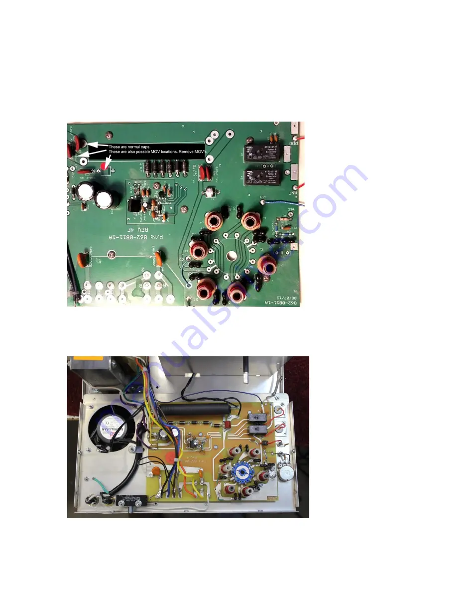
Gen III board around 2012 (has GDT pads, does not have problem relay line capacitor.):
Note this is a board I submitted to MFJ I recommended stopping MOV use. The actual production board may
have been altered from this layout once it left my control
(Fig 13)
This is the working position for all back panels. This is a correctly wired back panel. The back panel easily slips
backwards off the switch drive without any wire removal. This is a two relay board and it has the string of bias
diodes:
(Fig. 14)


