two diodes are used. The goal is to be around 10-20mA quiescent current per tube. This would be 30-
60mA zero signal keyed idle current in the AL811, and 40-80mA idle in the AL811H
4.)
Add a higher surge rated negative rail clamp diode. This diode protects the grid and plate meters and
shunts. The original diode is a small 1N4001 series diode. The kit diode is much stronger and fails far less
often. This reduces the aggravation of protection diode failures
5.)
Add a 100k resistor from filament to ground, or to a place I provided in later AL811’s that Ameritron for
some reason never used. This prevents a weak “popping” noise in your receiver from intermittent gas
tube ionization with some GDT’s and tubes
6.)
Supplies an additional GDT if you want to further clamp the RF input line to the input circuit
7.)
You
should
remove MOV’s if they are defective or if they are readily accessible. MOV’s do not add
anything worthwhile in protection and MOV’s are failure prone. They are too far downstream and
beyond the choke to do any good for your exciter. If they fail they can cause problems
The AL811 three-tube model normally does not require dropping the back panel unless it has defective MOV’s to
service. The 811H back panel almost always has to be dropped. This is not a big deal if your particular unit was
wired correctly from the factory
. It is a little more work if the transformer wires have been cut too short.
Always make sure the amplifier is unplugged and the capacitors are discharged before starting
this modification procedure. Never attempt to make any repair on the amp with it powered up
and the cover disconnect overridden. There are LETHAL VOLTAGES present inside the amplifier.
In all cases be careful and work slowly.
811PK
Last Edited 6/15/2021
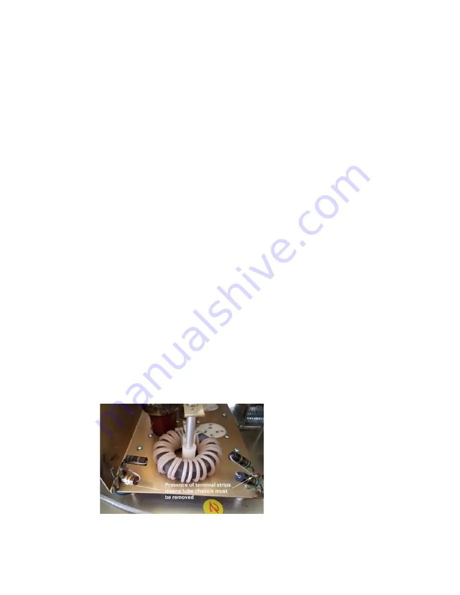
Amplifiers with these terminal strips and resistors must be upgraded for safety. This is an absolute because a
hard tube short will usually take out the resistors! Loss of resistors allows the arc to continue to the filament.
Refer to Fig. 2 & 3.
(
Fig 2)


