


52
18-CE03D1-1F-EN
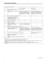
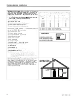
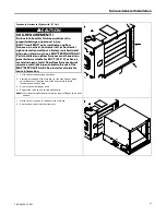
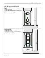
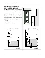
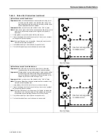
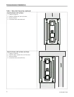
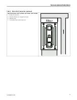
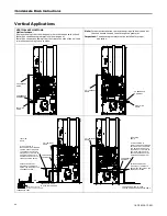
Table 4. Return Duct Connections (continued)
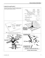
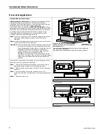
Upflow Furnace with Bottom and Side Returns Mounted on a
Ducted Pedestal with Side Return and Filter Box
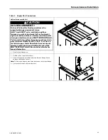
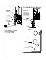
Important:
Make sure the condensate and thermostat wiring holes
are sealed on the cabinet side with the side return. The
plugs and grommets may need to be changed with those
on the opposite side of the cabinet.
Important:
Make sure not to cut the cabinet in the “No Cut” area.
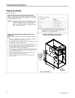
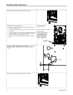
1.
Remove the bottom plate.
2.
Create ducting and set the furnace in place.
Note:
Use Optional BAYLIFT kit to lift furnace. Follow kit instructions.
Note:
The furnace bottom pedestal must be a minimum of 6” in
height.
3.
Match the filter cabinet flush to the back and bottom sides of the
furnace cabinet and secure in place with screws.
4.
Mark the two areas to be cut out for the return air.
5.
Cut out the two sections of the cabinet and BAYLIFT kit to be
removed.
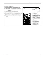
6.
Attach ducting to the filter box.
7.
The ducted pedestal will use ducted air from a remote location.
8.
Seal per local codes and requirements.
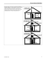
F
il
te
r
No Cut Area
Cutouts
17.5” Filter Cabinet with BAYLIFT Kit
Flush with back
of furnace cabinet
No Cut Area
Cutouts
21” Filter Cabinet with BAYLIFT Kit
Flush with back
of furnace cabinet
Содержание S9V2B040U3VSAB
Страница 12: ...12 18 CE03D1 1F EN Outline Drawings Upflow Furnace B Size Cabinet...
Страница 13: ...18 CE03D1 1F EN 13 Upflow Furnace C Size Cabinet O Ou ut tl li in ne e D Dr ra aw wi in ng gs s...
Страница 14: ...14 18 CE03D1 1F EN Upflow Furnace D Size Cabinet O Ou ut tl li in ne e D Dr ra aw wi in ng gs s...
Страница 15: ...18 CE03D1 1F EN 15 Downflow Furnace B Size Cabinet O Ou ut tl li in ne e D Dr ra aw wi in ng gs s...
Страница 16: ...16 18 CE03D1 1F EN Downflow Furnace C Size Cabinet O Ou ut tl li in ne e D Dr ra aw wi in ng gs s...
Страница 105: ...18 CE03D1 1F EN 105 N No ot te es s...
Страница 106: ...106 18 CE03D1 1F EN N No ot te es s...
Страница 107: ...18 CE03D1 1F EN 107 N No ot te es s...


