background image

Page 1

UNIT INFORMATION

UNIT INFORMATION

S e r v i c e   L i t e r a t u r e

©2016 Lennox Industries, Inc. 


 WARNING

I

mproper installation, adjustment, alteration, 

service or maintenance can cause property damage, 

personal injury or loss of life. Installation and service 

must be performed by a licensed professional HVAC 

installer (or equivalent), service agency or the gas 

supplier.

 CAUTION

As with any mechanical equipment, contact with 

sharp sheet metal edges can result in personal 

injury. Take care while handling this equipment and 

wear gloves and protective clothing.

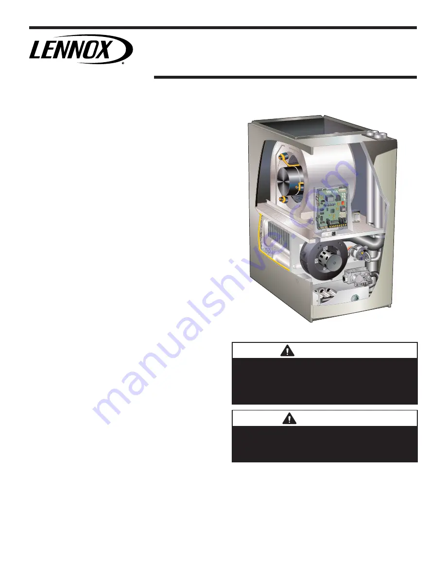
EL296DFE  series  units  are  high  efficiency  condensing 

gas furnaces used for downflow applications only, manu

-

factured with Lennox Duralok heat exchangers formed of 

aluminized steel. EL296DFE units are available in heating 

capacities of 44,000 to 110,000 Btuh and cooling applica

-

tions up to 5 tons. Refer to Product Specifications Manual 

for proper sizing.
Units are factory equipped for use with natural gas. Kits 

are available for conversion to LPG operation. EL296DFE 

model units are equipped with the SureLight

®

 two-stage 

constant torque integrated control. EL296DFE unit meets 

the California Nitrogen Oxides (NOx) Standards and Cal

-

ifornia Seasonal Efficiency requirements. All units use a 

redundant gas valve to assure safety shut-off as required 

by C.S.A.
All  specifications  in  this  manual  are  subject  to  change. 

Procedures  outlined  in  this  manual  are  presented  as  a 

recommendation only and do not supersede or replace lo

-

cal or state codes. In the absence of local or state codes, 

the guidelines and procedures outlined in this manual (ex

-

cept where noted) are recommendations only and do not 

constitute code.

TABLE OF CONTENTS

Specifications . . . . . . . . . . . . . . . . . . . . . . . . . . . . . Page 2
Blower Performance Data . . . . . . . . . . . . . . .  .  . . Page 4
I Unit Components . . . . . . . . . . . . . . . . . . . . .  . . . Page 6
II Installation  . . . . . . . . . . . . . . . . . . . . . . . . . . . . . Page 22
III Start Up  . . . . . . . . . . . . . . . . . . . . . . . . . . . . . . Page 45
IV Heating System Service Checks   . . . . . .   . . . Page 46
V Typical Operating Characteristics  . . . . . .  .  . . Page 49
VI Maintenance  . . . . . . . . . . . . . . . . . . . . . . . . . . Page 50
VII Wiring and Sequence of Operation      . . . . . . Page 53
VIII Field Wiring and Jumper Settings  . . .    . . . . Page 56
X Troubleshooting  . . . . . . . . . . . . . . . . . . . . . . . . Page 60

EL296DFE

Corp 1247-L10


Revised 06/2021

EL296DFE SERIES UNITS

Summary of Contents for EL296DF045XE36B

Page 1: ...use with natural gas Kits are available for conversion to LPG operation EL296DFE model units are equipped with the SureLight two stage constant torque integrated control EL296DFE unit meets the California Nitrogen Oxides NOx Standards and Cal ifornia Seasonal Efficiency requirements All units use a redundant gas valve to assure safety shut off as required by C S A All specifications in this manual...

Page 2: ...ap PVC pipe i d 3 4 3 4 3 4 3 4 with furnished 90 street elbow 3 4 slip x 3 4 Mipt 3 4 slip x 3 4 Mipt 3 4 slip x 3 4 Mipt 3 4 slip x 3 4 Mipt with field supplied PVC coupling o d 3 4 slip x 3 4 MPT 3 4 slip x 3 4 MPT 3 4 slip x 3 4 MPT 3 4 slip x 3 4 MPT Indoor Blower Wheel nom diameter x width in 10 x 8 11 1 2 x 10 10 x 10 11 x 11 Motor Type DC Brushless DC Brushless DC Brushless DC Brushless Mo...

Page 3: ...information Direct Vent Concentric US 2 in 71M80 69M29 3 in 60L46 Canada 2 in 44W92 44W92 3 in 44W93 Flush Mount US 2 2 1 2 or 3 in 51W11 51W11 Canada 2 2 1 2 or 3 in 51W12 51W12 Wall Close Couple US 2 in 22G44 3 in 44J40 44J40 Wall Close Couple WTK Canada 2 in 30G28 3 in 81J20 81J20 Roof Termination Flashing Kit no vent pipe 2 flashings 2 in 15F75 15F75 3 in 44J41 44J41 VENTING Flue Coupling 2 in...

Page 4: ...5 0 70 N A N A 1260 420 1050 295 915 245 570 150 0 80 N A N A 1220 430 1015 305 865 255 520 155 EL296DF090XE48C PERFORMANCE Less Filter External Static Pressure in w g Air Volume Watts at Various Blower Speeds High Black Medium High Brown Medium Blue Medium Low Yellow Low Red cfm Watts cfm Watts cfm Watts cfm Watts cfm Watts 0 00 1765 395 1565 265 1410 210 1290 175 1180 135 0 10 1745 410 1510 280 ...

Page 5: ...BLY shipping location CONSTANT TORQUE BLOWER MOTOR hidden OUTER ACCESS PANEL COMBUSTION AIR INDUCER BURNER BOX ASSEMBLY includes sensor rollout switches and ignitor GAS VALVE BLOWER DECK COLD END HEADER BOX PRIMARY LIMIT DuralokPlusTM HEAT EXCHANGER ASSEMBLY COMBUSTION AIR INDUCER PRESSURE SWITCH FIGURE 1 ...

Page 6: ...inte grated control The system consists of a ignition blower control figures 4 and 5 with control pin designations in ta bles 1 and 2 and ignitor figure 14 The control and ignitor work in combination to ensure furnace ignition and ignitor durability The control provides gas ignition safety checks and indoor blower control with two stage gas heating The furnace combustion air inducer gas valve and ...

Page 7: ... the DIP switch to ON for use with a single stage thermostat While in the single stage thermostat mode the burners will always fire on first stage heat The combustion air in ducer will operate on low speed and indoor blower will operate on low heat speed The unit will switch to second stage heat after a recognition period DIP switch 2 la beled SECOND STAGE DELAY is factory set in the OFF position ...

Page 8: ...COOL SIGNAL Y2 THERMOSTAT 2ND STAGE COOL SIGNAL O THERMOSTAT SIGNAL TO HEAT PUMP REVERSING VALVE L NOT USED DH NOT USED HUM UNPOWERED NORMALLY OPEN DRY CONTACTS LI 120 VAC INPUT TO CONTROL ACC 120 VAC OUTPUT TO OPTIONAL ACCESSORY NEUTRALS 120 VAC NEUTRAL 3 16 QUICK CONNECT TERMINALS FLAME SENSE SIGNAL HI COOL 24VAC HI HEAT 24VAC LO COOL 24VAC LO HEAT 24VAC PARK PARK COMMON 24VAC Flame Sense S4 DIP...

Page 9: ... 1 2 3 4 5 6 ON SureLight W1W2 G Y2 Y1 C C DH L O DS R W1 W2 G Y2 Y1 C C R L DH 7 PROTECTIVE PLASTIC FILM ON DIP SWITCHES MAY BE REMOVED FOR EASE IN SETTING OF DIP SW CUT ON BOARD LINK SOLDER TRACE COMPLETELY THROUGH BOTH LAYERS ON THE CONTROL BOARD LINKS CUT IN ERROR INSTALL A JUMPER ON THE APPROPRIATE TERMINALS ON THE TERMINAL STRIP 1 ON ON ON ON 90 SECOND HTG BLOWER OFF DELAY 1 2 3 4 5 6 7 ON 1...

Page 10: ...the sev en segment diagnostic LED This button is used to enable the Error Code Recall E mode and the Flame Signal F mode Press the button and hold it to cycle through a menu of options Every five seconds a new menu item will be displayed When the button is released the displayed item will be selected Once all items in the menu have been displayed the menu resumes from the beginning until the butto...

Page 11: ... proper range System resumes normal operation 5 seconds after fault recovered E114 Line voltage frequency out of range No 60 Hertz Power Check voltage and line power frequency Correct voltage and frequency problems System resumes normal operation 5 seconds after fault recovered E115 Low 24V Control will restart if the error recovers 24 Volt Power Low Range is 18 to 30 volts Check and correct volta...

Page 12: ...triction Resumes normal operation after fault is cleared E225 High pressure switch failed open Check pressure inches w c of high pressure switch closing on heat call Measure operating pressure inches w c Inspect vent and combustion air inducer for correct operation and restriction Resumes normal operation after fault is cleared E226 High pressure switch failed closed Check operation of high pressu...

Page 13: ...erating pressure inches w c Inspect vent and combustion air inducer for correct operation and restriction Clears when heat call finishes successfully E273 Soft lockout Exceeded maximum number of recycles Last recycle due to flame failure Check micro amperes of flame sensor using control diagnostics or field installed mode Clean or replace sensor Measure voltage of neutral to ground to ensure good ...

Page 14: ...rol The unit is shipped from the factory with a blower off delay of 90 seconds The blower off delay affects comfort and is adjustable to satisfy individual applications Adjust the blower off de lay to achieve a supply air temperature between 90 and 110 F at the exact moment that the blower is de ener gized Longer off delay settings provide lower supply air temperatures shorter settings provide hig...

Page 15: ...bleshooting the Motor Troubleshooting the motor is an easy process Follow steps below 1 Shut off power to unit 2 Remove input plugs P48 and P49 from motor See figure 8 for troubleshooting procedure If correct voltage is present in tests 1 and 2 and motor is not operating properly replace motor The motor is not field repairable If replacing the indoor blower motor or blower wheel is necessary place...

Page 16: ...eed tap used for continuous fan 1 2 3 4 or 5 on input plug P49 If 24 volts is not present problem may be up stream of plug P49 Proceed to test 4 Multi Meter set to VAC 12 0 12 0 24 Multi Meter set to VAC ent problem is with the harness If voltage is not present problem may be may be with the integrated control Check for 120 volts across terminals L1 and Neutrals on the integrated control If voltag...

Page 17: ...oximately the same resistance within an ohm 3 Check to see if the blower wheel spins freely Motor Test FIGURE 11 TABLE 8 Scale Measurement range inwords ohms 2 M two megohm two million ohms 0 2 000 000 200 K two hundred kilo ohm two hun dred thousand ohms 0 200 000 20 K twenty kilo ohm twenty thousand ohms 0 20 000 2 K two kilo ohm two thousand ohms 0 2 000 200 two hundred ohms 0 200 Motor Module ...

Page 18: ... Rollout Switches S47 Flame rollout switch is a high temperature limit located on top of the burner box one on each side See figure 14 The limit is a N C SPST manual reset limit When S47 senses rollout the circuit breaks and the ignition control immediately stops ignition and closes the gas valve Roll out can be caused by a blocked heat exchanger flue or lack of combustion air The wwswitch is fact...

Page 19: ...Page 19 HEATING COMPONENTS Intake Air Top Cap Sensor Rollout Switch Rollout Switch Burner Assembly Ignitor Manifold And Gas Orifices Two Stage Gas Valve Burner Box Cover FIGURE 14 ...

Page 20: ...volts Test 2 Check ignitor for correct resistance Seperate the 2 pin jack plug near the manifold and check resistance of ignitor at the plug Reading should be between 39 and 70 ohms If the reading is correct then the problem is with the wiring between the jack plug and the control If reading is not correct the issue is the ignitor Meter set to ohms Test 1 Check ignitor circuit for correct resistan...

Page 21: ...first and second stage located on the CEHB The switch is connected to the cold end header box by means of flexible silicone hoses It monitors negative differential pressure across the cold end header box orifice The switches are a single pole single throw pressure switches electrically connected to the integrated control The purpose of the switches is to prevent burner operation if the combustion ...

Page 22: ... use all purpose cement to bond ABS PVC or CPVC pipe when using fittings and pipe made of the same materials Use transition solvent cement when bonding ABS to either PVC or CPVC Low temperature solvent cement is recommended during cooler weather Metal or plastic strapping may be used for vent pipe hangers Uniformly apply a liberal coat of PVC primer for PVC or use a clean dry cloth for ABS to clea...

Page 23: ...ly to side vent sealing plates 2 as shown in FIGURE 19 12 Install the side vent sealing plates and gaskets on the exterior of the cabinet as shown in FIGURE 19 Secure with six mounting screws four reused and two provided from bag assembly Holes are pre punched in the parts and cabinet no drilling is required 13 Install sheet metal screws provided to seal extra two holes in cabinet not used with si...

Page 24: ...ES NOTE Standard Terminations do not include any vent pipe or elbows external to the structure Any vent pipe or elbows external to the structure must be included in total vent length calculations See vent length tables Kits must be properly installed according to kit instructions 1Requires field provided outdoor 1 1 2 exhaust accelerator 2Concentric kits 71M80 and 44W92 include 1 1 2 outdoor accel...

Page 25: ... during assembly but not after pipe is fully inserted to distribute cement evenly DO NOT turn ABS or cellular core pipe NOTE Assembly should be completed within 20 seconds after last application of cement Hammer blows should not be used when inserting pipe 8 After assembly wipe excess cement from pipe at end of fitting socket A properly made joint will show a bead around its entire perimeter Any g...

Page 26: ...y exhaust fans such as range hoods and bathroom exhausts so they will operate at maximum speed Do not operate a summer exhaust fan Close fireplace dampers 4 Followthelightinginstructions Turnontheappliance that is being inspected Adjust the thermostat so that the appliance operates continuously 5 After the main burner has operated for 5 minutes test for leaks of flue gases at the draft hood relief...

Page 27: ...e standard roof and wall terminations described in section Exhaust Piping Terminations should be used Exhaust vent termination pipe is sized to optimize the velocity of the exhaust gas as it exits the termination Refer to TABLE 20 In some applications which permit the use of several dif ferent sizes of vent pipe a combination vent pipe may be used Contact Lennox Application Department for assis ta...

Page 28: ...Termination Elevation 4501 10 000 ft Number Of 90 Elbows Used 1 1 2 Pipe 2 Pipe 2 1 2 Pipe 3 Pipe Model Model Model Model 045 070 090 110 045 070 090 110 045 070 090 110 045 070 090 110 1 20 15 n a n a 71 56 34 n a 105 105 83 48 128 127 108 108 2 15 10 66 51 29 100 100 78 43 123 122 103 103 3 10 n a 61 46 24 95 95 73 38 118 117 98 98 4 n a 56 41 19 90 90 68 33 113 112 93 93 5 51 36 14 85 85 63 28 ...

Page 29: ...E 18 Maximum Allowable Exhaust Vent Length Using Ventilated Attic or Crawl Space For Intake Air in Feet NOTE Additional vent pipe and elbows used to terminate the vent pipe outside the structure must be included in the total vent length calculation Standard Termination at Elevation 0 10 000 ft Number Of 90 Elbows Used 1 1 2 Pipe 2 Pipe 2 1 2 Pipe 3 Pipe Model Model Model Model 045 070 090 110 045 ...

Page 30: ... pipe and intake pipe must be the same diameter 2 TRANSITION 2 1 1 2 045 070 Only DO NOT transition from larger to smaller pipe in horizontal runs of exhaust pipe Exhaust Exhaust FIGURE 23 TYPICAL INTAKE PIPE CONNECTIONS 2 2 TRANSITION 2 3 TRANSITION 3 2 2 or TOP VIEW EXHAUST INTAKE When transitioning up in pipe size use the shortest length of 2 PVC pipe possible NOTE Intake pipe and exhaust pipe ...

Page 31: ...e must be the same diameter Pipe Length 4 Maximum Not Furnished 2 2 Plate Furnished Street Ell Not Furnished FIGURE 25 TRANSITION 2 3 TOP VIEW 2 When transitioning up in pipe size use the shortest length of 2 PVC pipe possible NOTE Intake pipe and exhaust pipe must be the same diameter 2 Plate Furnished TYPICAL AIR INTAKE PIPE CONNECTIONS WITH RIGHT SIDE VENT OPTION 2 Street Ell Not Furnished FIGU...

Page 32: ...es CAUTION If this unit is being installed in an application with combustion air coming in from a space serviced by an exhaust fan power exhaust fan or other device which may create a negative pressure in the space take care when sizing the inlet air opening The inlet air opening must be sized to accommodate the maximum volume of exhausted air as well as the maximum volume of combustion air requir...

Page 33: ...223 1 NFPA 54 in U S A and current CSA B149 Natural Gas and Propane Installation Codes in Canada for details Position termination according to location given in figure 31 or 32 In addition position termination so it is free from any obstructions and 12 above the average snow accu mulation At vent termination care must be taken to maintain pro tective coatings over building materials prolonged expo...

Page 34: ...a 7 n a 13 n a 12 n a 3 in 1 1 2 2 8 8 7 7 1Refer to 99 Minimum Design Temperature table provided in the current edition of the ASHRAE Fundamentals Handbook 2 Poly Propylene vent pipe PP by Duravent and Centrotherm 3 Vent length in table is equivalent length Consider each elbow as 5ft of linear length NOTE Concentric terminations are the equivalent of 5 and should be considered when measuring pipe...

Page 35: ...n public property Clearance under veranda porch deck or balcony 12 Equal to or greater than soffit depth 3 feet 9m 12 3 feet 9m within a height 15 feet 4 5m above the meter regulator assembly 3 feet 9m 6 inches 152mm for appliances 10 000 Btuh 3kw 12 inches 305mm for appliances 10 000 Btuh 3kw and 100 000 Btuh 30kw 36 inches 9m for appliances 100 000 Btuh 30kw 3 feet 9m above if within 10 feet 3m ...

Page 36: ...randa porch deck or balcony 12 7 feet 2 1m 3 feet 9m within a height 15 feet 4 5m above the meter regulator assembly 3 feet 9m 6 inches 152mm for appliances 10 000 pliances 10 000 Btuh 3kw and 50 000 pliances 50 000 Btuh 15kw 6 inches 152mm for appliances 10 000 Btuh 3kw 12 inches 305mm for appliances 10 000 Btuh 3kw and 100 000 Btuh 30kw 36 inches 9m for appliances 100 000 Btuh 30kw 3 feet 9m abo...

Page 37: ...m separation requirement of intake and exhaust pipe DOES NOT apply 3 On roof terminations the intake piping should terminate straight down using two 90 elbows See FIGURE 33 4 Exhaust piping must terminate straight out or up as shown A reducer may be required on the exhaust piping at the point where it exits the structure to improve the velocity of exhaust away from the intake piping See TABLE 20 T...

Page 38: ...INATION 71M80 69M29 or 60L46 US 44W92 or 44W93 Canada INTAKE AIR EXHAUST AIR INTAKE AIR INTAKE AIR EXHAUST AIR OUTSIDE WALL GRADE CLAMP Not Furnished FIELD PROVIDED REDUCER MAY BE REQUIRED TO ADAPT DIFFERENT VENT PIPE SIZE TO TERMINATION Accelerator not required for 3 concentric FIGURE 37 EXHAUST VENT INTAKE AIR 5 1 2 140mm Front View 12 305mm 5 127mm 18 MAX 457mm EXHAUST VENT INTAKE AIR OPTIONAL ...

Page 39: ...12 305 mm Min 16 405 mm Max 6 152 mm Max 6 152 mm Min 24 610 mm Max 9 227 mm Min 12 305 mm Min 20 508 mm Max 6 152 mm Max Intake Elbow WALL SUPPORT B A D E B D E A ALTERNATE TERMINATIONS TEE FORTY FIVE DEGREE ELBOWS ONLY D C 12 1 2 E B A 1 The exhaust termination tee should be connected to the 2 or 3 PVC flue pipe as shown in the illustration Do not use an accelerator in applications that include ...

Page 40: ...exhaust pipe terminations on multiple furnaces must meet local codes NOTE Do tical discharge through an existing unused chimney or stack is required insert piping inside trated In any exterior portion of chimney the exhaust vent must be insulated STRAIGHT CUT OR ANGLE CUT IN DIRECTION OF ROOF SLOPE SHOULDER OF FITTINGS PROVIDE SUPPORT OF PIPE ON TOP PLATE EXTERIOR PORTION OF CHIMNEY INSULATE TO FO...

Page 41: ...led up to 5 feet away from the furnace Piping from furnace must slope down a minimum of 1 4 per ft toward trap NOTE Appropriately sized tubing and barbed fitting may be used for condensate drain Attach to the drain on the trap using a hose clamp See figure 45 Field Provided Drain Components Tubing Hose Clamp Barbed Fitting Elbow FIGURE 45 6 If unit will be started immediately upon completion of in...

Page 42: ...IGURE 48 IMPORTANT When combining the furnace and evaporator coil drains together the A C condensate drain outlet must be vented to relieve pressure in order for the furnace pressure switch to operate properly Furnace with Evaporator Coil Using a Common Drain Field Provided Vent 1 min 2 max above condensate drain Evaporator Drain Line vent required Condensate Drain Connection FIGURE 49 ...

Page 43: ...te Drain Connection In Unit Vent To Drain Condensate Drain Connection In Unit Optional Condensate Drain Connection OptionalDrainPipingFromTrap DrainTrapAssembly Furnished DrainTrap Assembly with 1 2 inch Piping DrainTrap Assembly with 3 4 inch Piping 1 2 inch 3 4 inch 1 25 mm Min 2 50 mm Max Above Top Of Condensate Drain Connection In Unit 1 25 mm Min 2 50 mm Max Above Top Of Condensate Drain Conn...

Page 44: ... inch Drain Pipe 90 Street Elbow 1 2 inch PVC Not Furnished Condensate Drain Connection In Unit Adapter 1 2 inch slip X 1 2 inch mpt Not Furnished Condensate Drain Connection In Unit Vent To Drain Condensate Drain Connection In Unit Drain Trap Assembly with 3 4 inch Piping Vent To Drain Furnished Optional Condensate Drain Connection Optional Drain Piping From Trap Drain Trap Assembly Furnished Dra...

Page 45: ...rimed with sufficient water to ensure proper condensate drain operation WARNING If you do not follow these instructions exactly a fire or explosion may result causing property damage personal injury or death Gas Valve Operation Figure 52 1 STOP Read the safety information at the beginning of this section 2 Set the thermostat to the lowest setting 3 Turn off all electrical power to the unit 4 This ...

Page 46: ... provides access to the supply pressure See figure 52 Back out the 3 32 hex screw one turn connect a piece of 5 16 tubing and connect to a manometer to measure supply pressure See table 24 for supply line pressure E Check Manifold Pressure NOTE Pressure test adapter kit 10L34 is available from Lennox to facilitate manifold pressure measurement A manifold pressure post located on the gas valve pro ...

Page 47: ...eration at higher altitudes See table 23 for gas conver sion and pressure switch kits See table 24 for manifold pressures TABLE 23 Conversion Kit and Pressure Switch Requirements at Varying Altitudes Unit Natural to LP Propane High Altitude Natural Burner Orifice Kit High Altitude LP Propane Burner Orifice Kit High Altitude Pressure Switch 0 7500 ft 7501 10 000 ft 7501 10 000 ft 4501 7500 ft 7501 ...

Page 48: ...tes a poor or partial ground Compare the readings to the table below If the readings exceed the maximum shown in table 26 make repairs before operating the furnace 2 In addition measure the AC voltage from Line Hot to Line Neutral spade terminals on the integrated con trol See figure 54 This voltage should be in the range of 97 to 132 Vac TABLE 25 Furnace Status Measurement VAC Expected Maximum Po...

Page 49: ...ATURE RISE Supply Duct Temperature Return Duct Temperature _ Temperature Rise FIGURE 55 C External Static Pressure 1 1 Tap locations shown in figure 56 2 Punch a 1 4 diameter hole in supply and return air plenums Insert manometer hose flush with inside edge of hole or insulation Seal around the hose with permagum Connect the zero end of the manometer to the discharge supply side of the system On d...

Page 50: ...during the winter and the indoor coil to freeze in the summer resulting in an increase in the number of service calls Before using any filter with this system check the specifications provided by the filter manufacturer against the data given in the appropriate Lennox Product Specifications bulletin Additional information is provided in Service and Application Note ACC002 August 2000 TABLE 26 Cabi...

Page 51: ...er assembly to cabinet Remove two screws from blower rail which secure top heat exchanger flange Remove heat exchanger from furnace cabinet 20 Back wash heat exchanger with soapy water solution or steam If steam is used it must be below 275 F 135 C 21 Thoroughly rinse and drain the heat exchanger Soap solutions can be corrosive Take care to rinse entire assembly 22 Reinstall heat exchanger into ca...

Page 52: ...pect the inside of the burners and crossovers for any blockage caused by foreign matter Remove any blockage 9 Reinstall the burner box assembly using the existing four screws Make sure that the burners line up in the center of the burner ports 10 Reconnect the sensor wire and reconnect the 2 pin plug to the ignitor wiring harness 11 Reinstall combustion air intake flexible connector if equipped se...

Page 53: ...Page 53 TYPICAL EL296DFE WIRING DIAGRAM ...

Page 54: ...tion the unit will switch to low fire 3 After the pre purge is complete a 20 second initial ignitor warm up period begins The combustion air inducer continues to operate at low speed 4 After the 20 second warm up period has ended the gas valve is energized on low fire first stage and ignition occurs At the same time the control module sends a signal to begin an indoor blower 30 second ON delay Whe...

Page 55: ...ergized on the low fire heating speed and the HUM contacts are energized The integrated control also initiates a second stage on delay factory set at 7 minutes adjustable to 12 minutes 5 If the heating demand continues beyond the secondstage on delay the integrated control energizes the combustion air inducer at high speed The control also checks the high fire second stage pressure switch to make ...

Page 56: ...CUT ANY ON BOARD LINKS S1 T STAT FURNACE TERM STRIP OUTDOOR UNIT 1 Heat 2 Cool NOTE Use DIP switch 2 to set second stage heat ON delay OFF 7 minutes ON 12 minutes ON CUT ON BOARD LINK W915 2 STAGE COMPR S1 T STAT FURNACE TERM STRIP OUTDOOR UNIT 1 Heat 2 Cool with t stat with humidity control NOTE Use DIP switch 2 to set second stage heat ON delay OFF 7 minutes ON 12 minutes ON CUT ON BOARD LINK W9...

Page 57: ...URNACE TERM STRIP OUTDOOR UNIT 2 Heat 2 Cool with t stat with humidity control OFF CUT ON BOARD LINK W915 2 STAGE COMPR CUT ON BOARD LINK W914 DEHUM OR HARMONY S1 T STAT FURNACE TERM STRIP OUTDOOR UNIT o 2 Heat 1 Cool with t stat with humidity control OFF CUT ON BOARD LINK W914 DEHUM OR HARMONY S1 T STAT FURNACE TERM STRIP OUTDOOR UNIT o 2 Heat 1 Cool OFF DO NOT CUT ANY ON BOARD LINKS S1 T STAT FU...

Page 58: ...P T STAT FURNACE TERM STRIP HEAT PUMP 67M41 Y H L Y2 D B L Y2 T T outdoor sensor Dual Fuel Two Stage Heat Pump ComfortSense thermostat w bilities Capable of 2 stage gas heat control OFF CUT ON BOARD LINK W951 HEAT PUMP CUT ON BOARD LINK W915 2 STAGE COMPR FURNACE TERM STRIP HEAT PUMP out blue 67M41 H L Y2 D B L Y2 T T outdoor sensor T STAT Connect W1 to W1 ONLY if using defrost tempering kit 67M41...

Page 59: ...MONY T STAT FURNACE TERM STRIP HEAT PUMP 67M41 Y H L Y2 D B L Y2 T T outdoor sensor Dual Fuel Two Stage Heat Pump ComfortSense thermostat w bilities Capable of 2 stage gas heat midification OFF CUT ON BOARD LINK W914 DEHUM OR HARMONY CUT ON BOARD LINK W951 HEAT PUMP CUT ON BOARD LINK W915 2 STAGE COMPR T STAT FURNACE TERM STRIP HEAT PUMP 67M41 H L Y2 D B L Y2 T T outdoor sensor Y2 out blue Connect...

Page 60: ...FF ON FOR 3 SEC MINIMUM NO YES FIRST LOW STAGE PRESSURE SWITCH CONTACTS OPEN NO GAS VALVE OFF COMBUSTION AIR INDUCER OFF INDOOR BLOWER OFF CONTROL REMAINS UNTIL PRESSURE SWITCH IS DETECTED OPEN STATUS ERROR CODE 2 4 YES GAS VALVE OFF COMBUSTION AIR INDUCER OFF INDOOR BLOWER OFF CONTROL WILL NOT ATTEMPT SECOND STAGE OPERATION DURING THIS HEAT DEMAND FIRST STAGE OPERATION WILL BE ATTEMPTED STATUS ER...

Page 61: ... 19 microamps GAS VALVE OFF COMBUSTION AIR INDUCER ON INDOOR BLOWER OFF STATUS LED HEARTBEAT HAS CONTROL FAILED TO SENSE FLAME FOR FIVE CONSECUTIVE TRIES DURING A SINGLE HEAT DEMAND YES THERMOSTAT CALLS FOR HEAT STATUS LED HEARTBEAT Refer to box A on previous page YES FLAME PRESENT NO HAS CONTROL RESET IGNITION SEQUENCE FOUR 4 TIMES WATCHGUARD MODE STATUS ERROR CODE 4 3 YES CONTINUED ON NEXT PAGE ...

Page 62: ...IED GAS VALVE OFF COMBUSTION AIR INDUCER OFF FOLLOWING POST PURGE INDOOR BLOWER OFF WITH DELAY STATUS LED PULSE YES SECOND STAGE HEAT DEMAND SECOND STAGE HEAT DEMAND REQUIRED NO SECOND STAGE PRESSURE SWITCH CLOSED ABNORMAL FLASH CODE NOTE IF SECOND STAGE PRESSURE SWITCH WAS ORIGINALLY FOUND CLOSED ABNORMAL CODE WILL FLASH SECOND STAGE PRESSURE SWITCH CLOSED AT BEGINNING OF HEAT DEMAND STATUS ERROR...

Page 63: ...E YES YES FIRST AND SECOND STAGE HEAT DEMAND SATISFIED SIMULTANEOUSLY STATUS LED HEARTBEAT YES GAS VALVE OFF COMBUSTION AIR INDUCER OFF AFTER 5 SECOND LOW SPEED POST PURGE PERIOD INDOOR BLOWER OFF DELAY INITIATED ON LOW HEAT SPEED STATUS LED HEARTBEAT DEMAND FOR HEAT SATISFIED POWER ON STAND BY STATUS LED PULSE YES SECOND STAGE HEAT DEMAND SATISFIED STATUS LED HEARTBEAT NO GAS VALVE COMBUSTION AIR...

Page 64: ... GROUND YES NO INDOOR BLOWER ENERGIZED ON FIRST STAGE COOL SPEED AFTER 2 SECOND DELAY FIRST STAGE DEMAND FOR COOL SATISFIED NO THERMOSTAT CALLS FOR SECOND STAGE COOL COMPRESSOR AND CONDENSER FAN DE ENERGIZED INDOOR BLOWER DE ENEGIZED YES INDOOR BLOWER RAMPS UP TO SECOND STAGE COOL SPEED SECOND STAGE DEMAND FOR COOL SATISFIED YES UNIT RETURNS TO FIRST STAGE COOL SIGNAL IMPROPER GROUND AT LED CONTRO...

Page 65: ...GE HEAT DEMAND SATISFIED YES NO THERMOSTAT CALLS FOR SECOND STAGE HEAT YES INDOOR BLOWER SWITCHES TO HIGH HEAT SPEED AFTER 30 SECOND RECOGNITION PERIOD SECOND STAGE HEAT DEMAND SATISFIED YES YES INDOOR BLOWER RAMPS DOWN TO LOW HEAT SPEED INDOOR BLOWER RAMPS TO FIRST STAGE COOLING SPEED AFTER A 2 SECOND DELAY FIRST STAGE COOL DEMAND SATISFIED YES NO SECOND STAGE COOL DEMAND SATISFIED INDOOR BLOWER ...

Reviews: