background image

10

18-CE03D1-1F-EN

Furnace Installation Guidelines

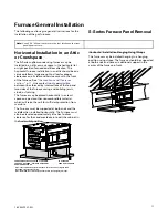
The following sections give general guidelines for the
installation of the gas furnaces.

Safety Practices and Precautions

The following safety practices and precautions must be
followed during the installation, servicing, and
operation of this furnace.

1. Use only with the type gas approved for this

furnace. Refer to the furnace rating plate.

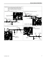
2. Install the furnace only in a location and position as

specified in “Locations and Clearances” of these
instructions.

3. Provide adequate combustion and ventilation air to

the furnace space as specified in “Air for
Combustion and Ventilation” of these instructions.

4. Combustion products must be discharged

outdoors. Connect this furnace to an approved vent
system only, as specified in the “Venting” section
of these instructions.

5. Never test for gas leaks with an open flame. Use a

commercially available soap solution made
specifically for the detection of leaks to check all
connections, as specified in the “Gas Piping”
section of these instructions.

6. Always install the furnace to operate within the

furnace’s intended temperature-rise range with a
duct system which has an external static pressure
within the allowable range, as specified on the unit
rating plate. Airflow within temperature rise for cfm
versus static is shown in the Service Facts
accompanying this furnace.

7. When a furnace is installed so that the supply ducts

carry air circulated by the furnace to areas outside
the space containing the furnace, the return air shall
also be handled by a duct(s) sealed to the furnace
casing and terminating outside the space
containing the furnace.

8. A gas-fired furnace for installation in a residential

garage must be installed as specified in "Location
and Clearances" section of these instructions.

9. The furnace may be used for temporary heating of

buildings or structures under construction only
when the following conditions have been met:

a. The furnace venting system must be complete

and installed per manufacturer’s instructions.

b. The furnace is controlled only by a room

Comfort Control (no field jumpers).

c. The furnace return air duct must be complete

and sealed to the furnace.

d. The furnace input rate and temperature rise

must be verified to be within the nameplate
marking.

e. A minimum 4” MERV 11 air filter must be in

place.

f.

100% of the furnace combustion air requirement
must come from outside the structure.

g. The Furnace return air temperature range is

between 45 and 80 Fahrenheit.

80% models = 55°F

90%+ models = 45°F

h. Clean the furnace, duct work, and components

upon substantial completion of the construction
process, and verify furnace operating conditions
including ignition, input rate, temperature rise,
and venting, according to the manufacturer’s
instructions.

10. IIn

n tth

he

e C

Co

om

mm

mo

on

nw

we

ea

alltth

h o

off M

Ma

assssa

acch

hu

usse

ettttss,, tth

hiiss

p

prro

od

du

ucctt m

mu

usstt b

be

e g

ga

ass p

piip

pe

ed

d b

by

y a

a L

Liicce

en

nsse

ed

d

P

Pllu

um

mb

be

err o

orr G

Ga

ass F

Fiitttte

err..

This furnace is certified to leak 2% or less of nominal air
conditioning CFM delivered when pressurized to .5”
water column with all inlets, outlets, and drains sealed.

General Guidelines

The manufacturer assumes no responsibility for
equipment installed in violation of any code or
regulation.

It is recommended that Manual J of the Air
Conditioning Contractors Association (ACCA) or A.R.I.
230 be followed in estimating heating requirements.
When estimating heating requirements for installation
at Altitudes above 2000 ft., remember the gas input
must be reduced. See Combustion and Input Check.

M

Ma

atte

erriia

all iin

n tth

hiiss ssh

hiip

pm

me

en

ntt h

ha

ass b

be

ee

en

n iin

nssp

pe

ecctte

ed

d a

att tth

he

e

ffa

acctto

orry

y a

an

nd

d rre

elle

ea

asse

ed

d tto

o tth

he

e ttrra

an

nssp

po

orrtta

attiio

on

n a

ag

ge

en

nccy

y

w

wiitth

ho

ou

utt kkn

no

ow

wn

n d

da

am

ma

ag

ge

e.. IIn

nssp

pe

ecctt e

ex

xtte

erriio

orr o

off cca

arrtto

on

n

ffo

orr e

ev

viid

de

en

ncce

e o

off rro

ou

ug

gh

h h

ha

an

nd

dlliin

ng

g iin

n ssh

hiip

pm

me

en

ntt..

U

Un

np

pa

acckk cca

arre

effu

ulllly

y a

afftte

err m

mo

ov

viin

ng

g e

eq

qu

uiip

pm

me

en

ntt tto

o

a

ap

pp

prro

ox

xiim

ma

atte

e llo

occa

attiio

on

n.. IIff d

da

am

ma

ag

ge

e tto

o cco

on

ntte

en

nttss iiss

ffo

ou

un

nd

d,, rre

ep

po

orrtt tth

he

e d

da

am

ma

ag

ge

e iim

mm

me

ed

diia

atte

elly

y tto

o tth

he

e

d

de

elliiv

ve

erriin

ng

g a

ag

ge

en

nccy

y..

Codes and local utility requirements governing the
installation of gas fired equipment, wiring, plumbing,
and flue connections must be adhered to. In the
absence of local codes, the installation must conform
with latest edition of the National Fuel Gas Code ANSI
Z223.1 / NFPA 54 • National Installation Code, CAN/CGA
B149.1. The latest code may be obtained from the
American Gas Association Laboratories, 400 N. Capitol
St. NW, Washington D.C. 20001.
1-800-699-9277 or www.aga.org.

These furnaces have been classified as CATEGORY IV
furnaces in accordance with latest edition of ANSI
Z21.47 standards • CSA 2.3. Category IV furnaces
operate with positive vent static pressure and with a

Содержание S9V2B040U3VSAB

Страница 1: ...ti ib bl le e t to o H Ho or ri iz zo on nt ta al l R Ri ig gh ht t o or r H Ho or ri iz zo on nt ta al l L Le ef ft t S9V2B040U3VSAB S9V2B060U3VSAB S9V2B080U4VSAB S9V2C100U4VSAB S9V2D120U5VSAB D Do...

Страница 2: ...R R E EX XP PL LO OS SI IO ON N H HA AZ ZA AR RD D F Fa ai il lu ur re e t to o f fo ol ll lo ow w t th hi is s W Wa ar rn ni in ng g c co ou ul ld d r re es su ul lt t i in n d da an ng ge er ro ou u...

Страница 3: ...r d de ea at th h D Do o N NO OT T a at tt te em mp pt t t to o m ma an nu ua al ll ly y l li ig gh ht t t th he e f fu ur rn na ac ce e W WA AR RN NI IN NG G C CA AR RB BO ON N M MO ON NO OX XI ID D...

Страница 4: ...e ef fo or re e s se er rv vi ic ci in ng g f fi il lt te er rs s t to o a av vo oi id d c co on nt ta ac ct t w wi it th h m mo ov vi in ng g p pa ar rt ts s W WA AR RN NI IN NG G C CA AR RB BO ON N...

Страница 5: ...il lu ur re e t to o f fo ol ll lo ow w t th hi is s C Ca au ut ti io on n c co ou ul ld d r re es su ul lt t i in n p pr ro op pe er rt ty y d da am ma ag ge e o or r p pe er rs so on na al l i in n...

Страница 6: ...t ti io on ns s D De et te er rm mi in ne e t th he er re e i is s n no o b bl lo oc ck ka ag ge e o or r r re es st tr ri ic ct ti io on n l le ea ak ka ag ge e c co or rr ro os si io on n o or r o o...

Страница 7: ...e ed d T Th he e 9 90 0 e el lb bo ow w c co on nn ne ec ct ti io on n t to o v ve er rt ti ic ca al l p pi ip pe e m mu us st t b be e s se ea al le ed d t to o p pr re ev ve en nt t c co on nd de en...

Страница 8: ...ield Wiring 58 59 Condensate Drain Instructions 61 61 Vertical Applications 62 Horizontal Applications 66 General Start up and Adjustment 67 Preliminary Inspections 67 Lighting Instructions 67 Control...

Страница 9: ...d requires specific knowledge and training Improperly installed adjusted or altered equipment by an unqualified person could result in death or serious injury When working on the equipment observe all...

Страница 10: ...F h Clean the furnace duct work and components upon substantial completion of the construction process and verify furnace operating conditions including ignition input rate temperature rise and venti...

Страница 11: ...nches of clearance between the furnace combustion air openings in the front panel and any closed panel or door provided 5 Are the ventilation and combustion air openings large enough and will they rem...

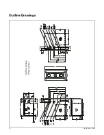
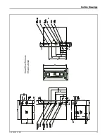
Страница 12: ...12 18 CE03D1 1F EN Outline Drawings Upflow Furnace B Size Cabinet...

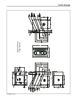
Страница 13: ...18 CE03D1 1F EN 13 Upflow Furnace C Size Cabinet O Ou ut tl li in ne e D Dr ra aw wi in ng gs s...

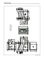
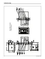
Страница 14: ...14 18 CE03D1 1F EN Upflow Furnace D Size Cabinet O Ou ut tl li in ne e D Dr ra aw wi in ng gs s...

Страница 15: ...18 CE03D1 1F EN 15 Downflow Furnace B Size Cabinet O Ou ut tl li in ne e D Dr ra aw wi in ng gs s...

Страница 16: ...16 18 CE03D1 1F EN Downflow Furnace C Size Cabinet O Ou ut tl li in ne e D Dr ra aw wi in ng gs s...

Страница 17: ...urnace may be placed horizontally in a crawl space on a pad or other noncombustible material which will raise the unit for sufficient protection from moisture The Furnace must be supported at both end...

Страница 18: ...s Line Grommet 1 8 NPT Test Fitting Upflow furnace with gas piping on right side Automatic Gas Valve with Manual Shut off Main Manual Shut off Valve Ground Union Joint Drip Leg Gas Line Grommet 1 8 NP...

Страница 19: ...1 8 NPT Test Fitting Horizontal left furnace with gas piping out right side Automatic Gas Valve with Manual Shut off Main Manual Shut off Valve Ground Union Joint Drip Leg Gas Line Grommet 1 8 NPT Tes...

Страница 20: ...ing its individual manual shut off valve during any pressure testing of the gas supply piping system at test pressures equal to or less than 1 2 psig 3 5 kPa Note Maximum pressure to the gas valve for...

Страница 21: ...utility company and compare to the nameplate rating This must not exceed the nameplate rating Gas Flow in Cubic Feet Per Hour 2 Cubic Foot Dial Sec Flow Sec Flow Sec Flow Sec Flow 10 732 31 236 52 141...

Страница 22: ...high altitude d Replace and tighten the regulator cover screw securely 6 Adjust 1st stage gas heat by removing the low LO adjustment regulator cover screw a To increase outlet pressure turn the regula...

Страница 23: ...MBER 44 ORF00501 54 ORF00555 45 ORF00644 55 ORF00693 46 ORF00909 56 ORF00907 47 ORF00910 57 ORF00908 48 ORF01099 58 ORF01338 49 ORF00503 59 ORF01339 50 ORF00493 Turn the main Gas Valve toggle switch w...

Страница 24: ...em must not be interchanged with other vent systems or unlisted pipe or fittings Plastic components specified primers and glues must be from a single system manufacturer and not intermixed with other...

Страница 25: ...may occur will now drain outside of the home The combustion air outlet piping must remain sloped back to the furnace Option 1 Slope equals 1 4 per foot To an approved vented drain Combustion air inta...

Страница 26: ...Tee Combustion air intake Combustion air exhaust Primary drain vent stack must terminate below the bottom of the condensate trap Option 3 Side combustion air intake If sloping the combustion air intak...

Страница 27: ...structure However the longest individual pipe will decide the value for the longest allowable equivalent vent inlet air length as shown in the vent length table Note For single pressure zone applicat...

Страница 28: ...ons for different types of 2 and 3 size pipe and fittings that meet these requirements The materials listed are various grades of PVC CPVC ABS PolyPro by DuraVent Z Dens by Novaflex Group Innoflue by...

Страница 29: ...the Furnace be connected and sealed with high temperature RTV This will enable the pipes to be removed later without cutting Be sure to properly support these joints Commercially available solvent cem...

Страница 30: ...ASTM STANDARD PIPE TYPE ALLOWABLE TEMPERATURE F MARKING D2661 SCH 40 DWV 180 ASTM D2661 F628 SCH 40 DWV CELLULAR CORE 180 ASTM F628 PolyPro by DuraVent Z Dens by Novaflex Group Innoflue by Centrother...

Страница 31: ...imum vent length for all models 15 equivalent 4 DO NOT MIX PIPE DIAMETERS IN THE SAME LENGTH OF PIPE OUTSIDE THE FURNACE CABINET Except adapters at the top of the furnace If different inlet and vent p...

Страница 32: ...ing coupling it is used for 3 vent pipe installation Make sure the marking TOP is located on the top side of the pipe in horizontal venting applications The straight side of the coupling must be on bo...

Страница 33: ...HROUGH COMBUSTIBLE WALLS Pitch 1 4 Inch Per Foot CLEARANCE 0 ACCEPTABLE FOR PVC VENT PIPE 1 ACCEPTABLE FOR TYPE 29 4C STAINLESS STEEL VENT PIPE 12 MINIMUM ABOVE NORMALLY EXPECTED SNOW ACCUMULATION LEV...

Страница 34: ...in the same pressure zone Important Maintain 12 minimum clearance above highest anticipated snow level or grade whichever is greater Note All distances are centerline to centerline 6 Min 24 Max 12 Mi...

Страница 35: ...in 3 feet of the vent terminal The vent for this appliance shall not terminate 1 Over public walkways or 2 Near soffit vents or crawl space vents or other areas where condensate or vapor could create...

Страница 36: ...t the time of completion of installation the owner shall have a period of thirty 30 days to comply with the above requirements provided however that during said thirty 30 day period a battery operated...

Страница 37: ...lding or the combustion air inlet to any other appliance 6 inches 15 cm for appliances 10 000 BTUH 3 kw 12 inches 30 cm for appliances 10 000 BTUH 3 kw and 100 000 BTUH 30 kw 36 inches 91 cm for appli...

Страница 38: ...building or the combustion air inlet to any other appliance 6 inches 15 cm for appliances 10 000 Btuh 3 kw 12 inches 30 cm for appliances 10 000 Btuh 3 kw and 100 000 Btuh 30 kw 36 inches 91 cm for ap...

Страница 39: ...ABOVE ROOF VENT COMBUSTION AIR BAYAIR30AVENTA BAYAIR30CNVENT REMOVE RIBS FROM CAP COMBUSTION AIR ROOF FLASHING BOOT FIELD SUPPLIED COMBUSTION AIR VENT ELBOW FIELD SUPPLIED MAINTAIN 12 IN 18 IN FOR CAN...

Страница 40: ...TABLE SUPPORT METHOD Venting Through an UNUSED Chimney Important Refer to Section 12 6 8 of NFPA 54 ANSI 223 1 2012 when routing vent piping through a chimney Important The single wall flue pipe joint...

Страница 41: ...choose to remodel or change the area which contains your Furnace Furnaces must have a free flow of air for proper performance Provisions for combustion and ventilation air shall be made in accordance...

Страница 42: ...rranties are not available in some instances Extended warranty does not cover repairs to equipment installed in establishments with corrosive atmospheres including but not limited to dry cleaners beau...

Страница 43: ...e with the outdoors Refer to the Minimum Free Area in square inches for confined spaces table for minimum open areas required CONFINED SPACE AIR FROM OUTDOORS CONFINED SPACE OUTLET OUTDOOR AIR DUCTS I...

Страница 44: ...installed so that the supply ducts carry air circulated by the furnace to areas outside the space containing the furnace the return air shall also be handled by a duct s sealed to the furnace and ter...

Страница 45: ...KI IT TA AA A k ki it t C Co oi il ls s i in ns st ta al ll le ed d o on n u up pf fl lo ow w f fu ur rn na ac ce es s m mu us st t h ha av ve e d dr ra ai in n p pa an ns s t th ha at t a ar re e s...

Страница 46: ...k ki it t C Co oi il ls s i in ns st ta al ll le ed d o on n u up pf fl lo ow w f fu ur rn na ac ce es s m mu us st t h ha av ve e d dr ra ai in n p pa an ns s t th ha at t a ar re e s su ui it ta ab...

Страница 47: ...fu ur rn na ac ce es s m mu us st t h ha av ve e d dr ra ai in n p pa an ns s t th ha at t a ar re e s su ui it ta ab bl le e f fo or r 4 40 00 0 F F 2 20 05 5 C C o or r h ha av ve e a a m me et ta a...

Страница 48: ...ng at the back of the furnace cut the side flanges along perforations until past the end of the heat shield to avoid interference when bending 3 Bend furnace side flanges down 4 Support the furnace an...

Страница 49: ...no Coil Important A BAYBASE is required when installing the furnace on a combustible floor 1 Bend furnace flanges up 2 Attach ducting 3 Seal per local codes and requirements F Fu ur rn na ac ce e G G...

Страница 50: ...y An external overflow drain pan must be installed in all applications over a finished ceiling to prevent property damage Upflow Furnace with Bottom Return in Closet with Remote Filter 1 Remove the bo...

Страница 51: ...rom a remote location 3 Install filter at a remote location 4 Seal per local codes and requirements Upflow Furnace with Bottom Return Mounted on a Ducted Pedestal with Filter Box 1 Remove the bottom p...

Страница 52: ...rnace Follow kit instructions Note The furnace bottom pedestal must be a minimum of 6 in height 3 Match the filter cabinet flush to the back and bottom sides of the furnace cabinet and secure in place...

Страница 53: ...low Furnace with Two Side Returns Important One of the sides must have a transition to allow the condensate and thermostat wiring to exit the cabinet Important If a transition is not a viable option a...

Страница 54: ...p of the furnace 3 Install remote filter 4 Seal per local codes and requirements Downflow Furnace with Top Return and Plenum 1 Remove the top plate 2 Attach the plenum ducting to the top of the furnac...

Страница 55: ...Furnace with Top Return and Plenum with Filter Box 1 Remove the top plate 2 Attach the filter box to the top of the furnace 3 Attach ducting 4 Seal per local codes and requirements Filter F Fu ur rn...

Страница 56: ...rn Air Filter Installations All return air duct systems should provide for installation of return air filters 1 Determine the appropriate position to set the furnace in order to connect to existing su...

Страница 57: ...out Thin cloths should be placed over the registers and the furnace fan should be run for 10 minutes Don t forget to remove the cloths before you start the furnace 4 The horizontal installation of the...

Страница 58: ...IFC and connect wiring 2 The factory Y1 O jumper must remain in place for proper LED read out in cooling mode 3 Y1 and Y2 wiring from the thermostat must connect to the IFC for proper airflow and LED...

Страница 59: ...24 V FIELD WIRING 24 V FACTORY WIRING Furnace IFC BK JUMPER SEE NOTE 1 O BK BK Y2 Y1 Y1 B C B C W2 W1 W1 G G R R O Y1 B C Single Stage Thermostat Furnace Outdoor Unit No Transformer SEE NOTE 2 SEE NO...

Страница 60: ...OOLING HP D R B Outdoor Unit NOTES 1 Cut the BK jumper at the indoor unit After cutting the jumper power must be off or cycled on off on for the IFC to work properly 2 Requires an 850 control with sof...

Страница 61: ...resistant condensate pump must be used if a pump is required for a specific drain system C CA AU UT TI IO ON N W Wa at te er r D Da am ma ag ge e P Pr ro op pe er rt ty y D Da am ma ag ge e I It t i...

Страница 62: ...PRIMARY DRAIN VENT STACK MUST TERMINATE BELOW THE BOTTOM OF THE CONDENSATE TRAP IF THE FURNACE IS INSTALLED OVER A FINISHED CEILING OVERFLOW FROM THE PRIMARY DRAIN VENT STACK MUST FLOW INTO AN AUXILIA...

Страница 63: ...ondensate tubing off and connect the tubing to the condensate trap Install the condensate grommet into the bottom panel Cut to length as needed DOWNFLOW FURNACES WITH BOTTOM DRAIN CONDENSATE PIPED TO...

Страница 64: ...nsate drain trap 4 Cut off the excess tube and reinstall the end fitting to the drain hose BOTTOM HOLE MUST BE PLUGGED DOWNFLOW FURNACES LEFT SIDE DRAIN IF THE FURNACE IS INSTALLED OVER A FINISHED CEI...

Страница 65: ...1 16 hole drilled through the cabinet and insert into drain line hose Secure with the spring clip Note Seal around the condensate drain tubing where it exits the cabinet Cut hose Approx 4 11 16 DIAMET...

Страница 66: ...nsate will block drains resulting in furnace shutdown If the drain line cannot be installed in a conditioned space then UL listed heat tape should be applied as required to prevent freezing per manufa...

Страница 67: ...e e f fu ur rn na ac ce e To shut off For complete shutdown Turn the toggle or control switch located on the main gas valve inside the unit to the OFF position and the external main gas shutoff valve...

Страница 68: ...s and the options for venting the inlet and exhaust combustion air I Im mp po or rt ta an nt t When looking at the different orientations the direction of the combustion air exhaust in the illustratio...

Страница 69: ...ion air exhaust vented through left side Note Requires a hole to be drilled in the case Refer to the illustrations below to find the approved venting options for downflow furnace models Important The...

Страница 70: ...through vent outlet adaptor and insert into inducer outlet 2 Twist to insure PVC is fully inserted 3 Tighten the clamp on the end of the 45 degree elbow 4 Tighten the clamp on the outlet vent adapter...

Страница 71: ...t side vent outlet is not allowed because condensate will not drain Before proceeding lay unit on its back to make conversion easier 1 Disconnect all drain tubes from condensate trap Note When removin...

Страница 72: ...cabinet 1 Loosen the clamp holding the 45 elbow Remove the elbow and discard 1 Remove the three inducer mounting screws 2 Rotate inducer counter clockwise so that the inducer outlet aligns with the ex...

Страница 73: ...rotated position 1 Attach the vent outlet gasket to the vent outlet 2 Install vent outlet to top of cabinet using 2 screws supplied in the dock pack 3 Install vent inlet gasket and vent inlet using 4...

Страница 74: ...ion Important Trim the condensate pressure switch tubing to length to ensure there is no sag or trap created 2 Remove port cap at bottom of inducer and connect inducer condensate tubing Connect other...

Страница 75: ...the trap with your hand to prevent the trap from breaking Removing the trap before the hoses is also an option 2 Remove tubing from PS2 to cold header 3 Remove drain tubing from bottom of inducer hou...

Страница 76: ...the inducer so that the outlet is pointing vertically 3 Use the three screws to reattach the inducer to the cold header to 30 in lbs Do not overtighten F Fu ur rn na ac ce e C Co om mb bu us st ti io...

Страница 77: ...let 4 Reuse the two 3 plugs to seal the two 3 default openings on the top of the furnace 1 Attach the vent outlet gasket to the vent outlet 2 Install vent outlet to top of cabinet using 2 screws suppl...

Страница 78: ...irements Condensate Trap Installation 1 Reinstall the condensate adapter if it was earlier removed or ensure adapter is still in place Important The condensate adapter must be present for proper conde...

Страница 79: ...trap orientation and inducer port caps The figure to the right shows the furnace as it is sent from the factory Use the following steps to modify the furnace for horizontal left with top venting of c...

Страница 80: ...t 1 Remove the pressure switch bracket assembly 2 Remove the screw that holds PS2 rotate 90 degrees clockwise and reattach 3 Reattach the pressure switch bracket assembly F Fu ur rn na ac ce e C Co om...

Страница 81: ...et PVC pipe Note The vent outlet adapter is used for strain relief against the weight of the venting The clamp should be tightened after the internal connection is made Note If required transition to...

Страница 82: ...nsure there is a rise in the tubing to avoid condensed flue gases from entering pressure switch 2 Remove port cap on left side of inducer and connect inducer condensate tubing Connect other end of ind...

Страница 83: ...tubing from PS2 to cold header 3 Remove drain tubing from bottom of inducer housing 4 Remove rain gutter tubing from inducer outlet 5 Remove tubing from condensate pressure switch 6 Remove the screws...

Страница 84: ...sket and vent inlet using 4 screws supplied in the doc pack 1 Remove three inducer screws 2 Rotate the inducer so that the outlet is pointing vertically 3 Use the three inducer screws to reattach the...

Страница 85: ...nstall the combustion air inlet PVC pipe Note The vent outlet adapter is used for strain relief against the weight of the venting The clamp should be tightened after the internal connection is made No...

Страница 86: ...ndensate port trap 3 Hand tighten screw 1 Connect PS2 tubing to switch and new sensing location Important Trim the condensate pressure switch tubing to length to ensure there is no sag or trap created...

Страница 87: ...emove drain tubing from bottom of inducer housing 4 Remove rain gutter tubing from inducer outlet 5 Remove tubing from condensate pressure switch 6 Remove the screws that hold the condensate trap brac...

Страница 88: ...nto the cold header outlet located on the bottom left of the cold header 4 Rotate the inducer 180 degrees so that the elbow is pointing towards the left 5 Use the three inducer screws to reattach the...

Страница 89: ...vent inlet gasket and vent inlet using 4 screws supplied in the doc pack Note The vent outlet adapter is used for strain relief against the weight of the venting The clamp should be tightened after t...

Страница 90: ...condensate drain operation 2 Install condensate trap into new location by fitting into grommet and aligning the hole on the condensate trap with the hole labeled HR Important When installing a 21 0 w...

Страница 91: ...ary 3 Install previously removed port cap onto bottom port of the inducer As viewed in upflow 4 Connect condensate pressure switch tubing to pressure port on the condensate trap Important Cut to lengt...

Страница 92: ...the doc pack 1 Slide PVC pipe through vent outlet adaptor and insert into inducer outlet 2 Twist to insure PVC is fully inserted 3 Tighten the two clamps 4 Install the combustion air inlet PVC pipe N...

Страница 93: ...n air Important Right side vent outlet is not allowed because condensate will not drain Before proceeding lay unit on its back to make conversion easier 1 Disconnect all drain tubes from condensate tr...

Страница 94: ...ion air exhaust and inlet 2 Reuse the two 3 plugs to seal the two 3 default openings on the top of the cabinet 1 Loosen the clamp holding the 45 elbow Remove the elbow and discard F Fu ur rn na ac ce...

Страница 95: ...to 30 in lbs Do not overtighten 1 Remove the pressure switch bracket assembly 2 Remove the screw that holds PS2 rotate 90 degrees counterclockwise and reattach 3 Reattach the pressure switch bracket a...

Страница 96: ...applications may use BAYREDUCE to meet ULC S636 requirements See Horizontal Venting section for proper orientation of 2 x 3 offset coupling 1 Connect PS2 tubing to switch and sensing location Importa...

Страница 97: ...ny fan off delays to finish should be seen on the display Scroll to the selected Menu item by momentarily depressing the MENU key and then depress the OPTION key to the desired se ng Then momentarily...

Страница 98: ...e nearest 10 cfm NOTES 1 The menu status displayed is solely dependent on the input of 24VAC that is applied to the low voltage terminal strip 2 The status will alternate between the system mode and t...

Страница 99: ...r 10 seconds Turns on the circula ng blower on 2nd stage gas heat speed for 10 seconds The above sequence will repeat two more mes unless the Run Test Mode is exited see above Important The Run Test M...

Страница 100: ...Second Stage Cooling Xp First Stage Heat Pump Xp2 Second Stage Heat Pump dFt Defrost Mode Menu Options err Active Alarm Menu L6F Last 6 Faults To clear Hold Option button down for 5 seconds Cr Code R...

Страница 101: ...enu by pressing the Option key 3 Hold the Option key for at least 5 seconds 4 Release and a set of 3 dashes with be seen 3 times This confirms the faults have been cleared Resetting Factory Defaults 1...

Страница 102: ...rning routine seen as L LR R1 1 on the seven segment LED display X Xt t1 1 and L LR R1 1 will alternately be displayed until the learning routine has been successfully completed See Learning Routine s...

Страница 103: ...tacts open 13 When the temperature raises enough to satisfy the thermostat setting contacts R W1 will open 14 The gas valve relay will open closing the gas valve The inducer will continue to run for a...

Страница 104: ...lo os se es s a at t d de ef fa au ul lt t s sp pe ee ed d a The inducer speed is reduced every 2 seconds until PS1 opens b At the time PS1 opens the IFC stores the inducer RPM c The inducer RPM is t...

Страница 105: ...18 CE03D1 1F EN 105 N No ot te es s...

Страница 106: ...106 18 CE03D1 1F EN N No ot te es s...

Страница 107: ...18 CE03D1 1F EN 107 N No ot te es s...

Страница 108: ...lications For more information please visit www trane com or www americanstandardair com The manufacturer has a policy of continuous data improvement and it reserves the right to change design and spe...

Отзывы: