background image

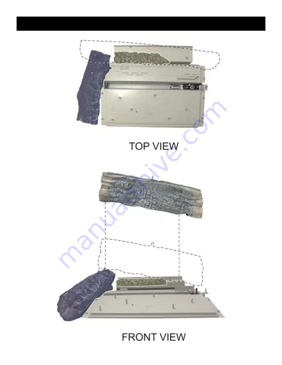
LOG PLACEMENT

3. 

Place Rear Top Log (C) onto Burner Pin 5 and the rear pin on Left Log (B).

Note: Ember material not shown for clarity.

35010-2-1015

Page 36

Содержание Intermittent Pilot ADVCX36FP70N-2

Страница 1: ...pors and liquids in the vi cinity of this or any other appliance WHAT TO DO IF YOU SMELL GAS Do not try to light any appliance Do not touch any electrical switch do not use any phone in your building Immediately call your gas supplier from a neighbor s phone Follow the gas supplier s instructions If you cannot reach your gas supplier call the fire department Installation and service must be per fo...

Страница 2: ...es 11 12 8 Install the fireplace See Pages 16 19 9 Connect the gas See Page 13 10 Connect the electricity See Page 15 11 Connect the venting system See Page 20 12 Install the optional remote system See Page 47 for Millivolt Systems and Page 52 for Intermittent Pilot Systems 13 Install the logs See Page 32 44 14 Light the fireplace and troubleshoot See Pages 48 49 for Millivolt Systems and 54 57 fo...

Страница 3: ... 31 Liner Placement 32 Glowing Embers 32 Log Identification 33 Log Placement 34 44 Millivolt System Appliances 45 51 Operating Instructions 45 46 Wiring Diagram 47 Lighting Instructions 48 Troubleshooting 49 Parts View 50 Parts List 51 Intermittent Pilot Appliances 52 59 Operating Instructions 52 Wiring Diagram 53 Lighting Instructions 54 Troubleshooting 55 57 Parts View 58 Parts List 59 All Appli...

Страница 4: ...They are standard hardware items and can be purchased at any local hardware store DVCX 36 42 FP3 SERIES DVCX 36 42 FP7 SERIES INDEX NUMBER DESCRIPTION QTY SUPPLIED 1 Rock Wool 2 2 Receptical Cover 2 3 Receptical 2 4 Flue Restrictor Assembly NAT or LP 1 5 Hardware Pack 1 6 AA Battery 4 7 AC Adaptor 1 Not Shown Log Set see Page 33 1 set Not Shown Fireplace 1 Not Shown Accessory Sheet 1 Not Shown Pro...

Страница 5: ...oper installation or use of the fireplace can cause serious injury or death from fire burns explosions or carbon monoxide poisoning The installation must conform with local codes or in the absence of local codes with the National Fuel Gas Code ANSIZ223 1 NFPA54 NaturalGasandPropaneInstallation Code or CSA B149 1 in Canada Available from the American National Standards Institute Inc 11 West 42nd St...

Страница 6: ...16 Depth 21 1 16 21 1 16 21 1 16 21 1 16 Gas Inlet Shutoff Valve pipe 1 2 NPT 1 2 NPT 1 2 NPT 1 2 NPT Vent Size 5 x 8 5 x 8 5 x 8 5 x 8 NOTE Air shutter settings are factory minimum settings Some venting configurations may require minor air shutter adjustments for optimum performance NOTE The glass used in your fireplace is ceramic glass If the glass is cracked or damaged in any way it should be r...

Страница 7: ...ive Floor Black ADVCX36 DVF42XKR Reflective Floor Black ADVCX42 FBB10 Blower Auto Variable Speed ADVCX 36 42 LK6 Lighting Kit 120V ADVCX 36 42 DCA1ABL Decorative Forged Andirons Black ADVCX 36 42 HEX HEAD SCREW 10 X 1 2 REMOTE CONTROL ACCESSORIES DESCRIPTION MODELS USED ON FRBC Battery Remote ON OFF ADVCX 36 42 FP 3 7 FRBTC Battery Remote Thermostat ADVCX 36 42 FP 3 7 TMW Wireless Wall Thermostat ...

Страница 8: ...box 28 3 8 32 3 8 H The height to the firebox standoffs 42 1 8 42 1 8 I Width from the left side of the box to the centerline of vent 19 1 8 23 1 8 J Depth from back of box to centerline of top vent 7 11 16 7 11 16 K Height from the bottom of the box to the gas line opening 2 2 L Depth from the front of the box to gas line opening 11 3 16 11 3 16 M Depth from rear of box to gas line opening 10 7 8...

Страница 9: ...L CHART FOR MAXIMUM MANTEL DEPTH SEE MANTEL CHART FOR MINIMUM HEIGHT OF MANTEL ABOVE UNIT STAND OFF 3 76mm HEIGHT ABOVE TOP OF FIREPLACE REAR STAND OFF SIDE STAND OFF Figure 1 Note Generic Firebox shown Mantel Chart TOP EDGE OF FIREPLACE OPENING INDEX LETTER DIMENSIONS in inches DISTANCE FROM TOP EDGE OF FIREPLACE OPENING HORIZONTAL DISTANCE FROM FIREPLACE FRONT VERTICAL A 12 25 1 2 B 10 25 1 2 C ...

Страница 10: ...is fireplace Empire Comfort Sys tems accepts no responsibility for damage or injuries Follow the television manufacturer s installation instructions including any recommendations regarding proximity to heat sources If you have a TV above your fireplace turn off the fireplace and let it cool completely before servicing or touching any buttons on the TV CLEARANCES Do not attach combustible material ...

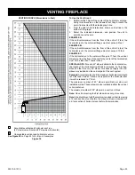
Страница 11: ...een the combustion air intake and the flue gas exhaust certain limitations as to vent configurations apply and must be strictly adhered to Figure 7 VENT TERMINATION CLEARANCES The graph showing the relationship between vertical and horizontal side wall venting will help to determine the various vent lengths allowable The horizontal vent run refers to the total length of vent pipe from the flue col...

Страница 12: ...1 cm 24 in 61 cm L Clearance above paved sidewalk or paved drive way located on public property 7 ft 2 13 m 7 ft 2 13 m E Clearance to unventi lated soffit 12 in 30 cm 12 in 30 cm M Clearance under veranda porch deck or balcony 12 in 30 cm 12 in 30 cm F Clearance to outside corner 6 in 15 cm 6 in 15 cm 1 In accordance with the current CSA B149 1 Natural Gas and Propane Instal lation Code G Clearan...

Страница 13: ... with a soap solution watching for bubbles on all exposed connections and if unexposed a pressure test should be made Never use an exposed flame to check for leaks Appliance must be disconnected from piping at inlet of control valve and pipe capped or plugged for pressure test Never pressure test with appliance connected control valve will sustain damage NOTE Themillivoltgascontrolsareequippedwith...

Страница 14: ...ertical run of 8 feet See details in Venting Section Note When installing this appliance against an exterior wall insulate to applicable insulation codes When you install your Direct Vent Fireplace in Room divider or Flat on wall corner positions a minimum of 6 inches clearance must be maintained from the perpendicular wall and the front edge of the appliance LOCATING FIREPLACE ...

Страница 15: ...ire to one side of the receptacle and white wire to opposite side of receptacle The ground wire should be attached to the green ground screw Install the receptacle into the junction box Attach cover plate Figure 13 IPI System Valve Models 1 Power for switched and live sides of receptacle must come from the same power source One circuit breaker on main panel must switch all power off 2 From the wal...

Страница 16: ...er installing firebox into framing the finished wall surface must cover the six inch opening above the firebox DIMENSIONS in inches Dim ADVCX36 ADVCX42 A 42 5 16 42 5 16 B 42 3 8 46 3 8 C 21 1 2 21 1 2 Figure 15 Framing and Finishing 1 Choose unit location 2 Frame in fireplace with a header across the top It is important to allow for finished face when setting the depth of the frame 3 Attach firep...

Страница 17: ...igure 19 NOTE A two inch clearance around pipe for the first twelve inches above the fireplace is required Finish the joint between the fireplace and wall with sealant rated at 300 degrees F or tile stone over the joint Figure 18 Horizontal Vent Clearances Figure 19 Flush Wall Installation Figure 20 Combustible Surround Installation Figure 21 Attention Cold climate installation recommendation When...

Страница 18: ... Fourcornersupports Example Fourconcretemasonryblocks These supports must be positioned so they contact all four perimeter edges on the bottom of the unit Securing the Vent Pipe to the Fireplace 1 Hand bend the tabs up on the Outer Wrapper Top Assembly as shown in Figure 22 Figure 22 2 Insert the first piece of pipe and secure with four screws through the tabs and into the pipe See Figures 23 and ...

Страница 19: ... 10 3 4 to 12 1 4 Figure 26 CORNER INSTALLATION VERTICAL 90 DEGREE ELBOW TO HORIZONTAL OUT THE WALL 12 minimum rise before elbow DIMENSIONS in inches Dim ADVCX36 ADVCX42 A 47 49 7 8 B 33 1 4 35 1 4 C 13 3 4 15 1 8 D 66 3 8 70 1 2 Figure 27 After installing the vent system install flue heat shield 1 Hand bend tabs on flue heat shield out 90 2 Attach to insulation box as shown in Figure 28 Figure 28...

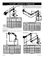
Страница 20: ...ize is the same NOTICE All outer connection joints must be sealed with aluminum tape screwsorsiliconesealantratedabove300 F 149 C Theinner flue joints do not require any sealant Figure 29 VENT SYSTEM IDENTIFICATION Special DV Vent Kits Available from Empire Comfort Systems Inc dealers DVVK 5TP Direct Vent Fireplace Vent Kit for Top Vent Thru the wall 4 to 6 inch wall thickness Includes 58DVA E90 5...

Страница 21: ... and recommended open ings for the flue restrictor Adjustments may be made for each par ticular installation Figure 30 Figure 31 The minimum hole location dimensions for through the wall horizontal installations with a 90 degree elbow and 12 inch rise off the top of the fireplace A FIREPLACE SERIES HARD ELBOW DIMENSIONS in inches A B C D ADVCX36 51 1 2 5 5 16 7 5 16 10 5 8 ADVCX42 51 1 2 5 5 16 7 ...

Страница 22: ...ng the hole it must be noted that the bottom of the cap must be 12 305mm above the ground level and top of the cap must be no less than 18 457mm below a combustible projection and no closer than 9 229mm to any wall running parallel to vent termination Figure 33 Below Grade Installation When it is not possible to meet the required vent termination clearances of 12 inches 305 mm above grade level a ...

Страница 23: ...each 45 elbow installed in the horizontal run the length of the horizontal run MUST be reduced by 18 inches Reduce 3 feet for every 90 elbow This does not apply if the 45 elbows are installed on the vertical part of the vent system Example Accordingtothechartthemaximumhorizontalventlength is 20 feet and if two 45 elbows are required in the horizontal vent it must be reduced to 17 feet The maximum ...

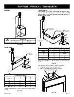
Страница 24: ... MAXIMUM 24 28 7 6 MAXIMUM Figure 37 Two 90 Elbows Note Subtract 3 feet from the total horizontal measurement for each 90 elbow installed horizontally Subtract 1 1 2 feet from the total horizontal measurement for each 45 elbow installed hori zontally 1 MININUM INSTALLED HORIZONTALLY B A EXAMPLE VENT RUNS INITIAL PIPE LENGTH A Vertical B Horizontal 3 6 3 5 11 MAXIMUM 4 7 3 5 17 MAXIMUM 4 6 7 9 5 17...

Страница 25: ...btract 3ft 914 mm from the total horizontal measure ment for each 90 elbow installed horizontally Subtract 1 1 2 ft 457 mm from the total horizontal measurement for each 45 el bow installed horizontally Dimensions in Feet A B MIN 4 8 17 6 10 15 1 2 8 12 14 10 14 13 MAX 12 16 12 Maximum horizontal run is 100 of vertical but cannot exceed 17 feet Figure 42 After installing the vent system install fl...

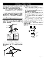
Страница 26: ...creased In high wind conditions nearby trees adjoining roof lines steep pitched roofs and other similar factors can result in poor draft or down drafting In these cases increasing the vent height may solve this problem Figure 45 General Maintenance Inspect venting system semi annually as follows 1 Check for corrosion areas of the venting system exposed to the elements These will appear as rust spo...

Страница 27: ...ould the outside walls of your home This is especially important in cold climates Upon completion of chase framing install the vent system by following the instructions in this manual Figure 47 Vertical Through the Roof Applications Your Gas Fireplace has been approved for a Vertical installations up to 40 feet in height b Two sets of 45 degree elbow offsets within these vertical installations Fro...

Страница 28: ...gh an interior wall an exterior wall or a ceiling These firestops act as a firebreak heat shield and as a means to insure that minimum clearances are maintained to the vent system Horizontal Firestops Horizontal runs in the vent system which pass through either interior or exterior walls require the use of wall firestops on both sides of the wall through which the vent passes Position the firestop...

Страница 29: ...reviously cut and framed hole See Figure 52 If the area above the ceiling is an attic position and secure the firestop on top of the previously framed hole See Figure 53 NOTE Remove insulation from the framed area in the attic before installing the firestop and or vent pipes Figure 51 Figure 52 Figure 53 Finishing Finish the walls with the material of your choice Figure 2 on Page 9 showstheminimum...

Страница 30: ...ual distance between spring spacers Figure 54 5 FLEX VENT PIPE SPACER SPRING 8 FLEX VENT PIPE Figure 55 3 Attach a 6 piece of hard pipe to raise the connection point above the unit 4 Use existing 8 diameter inlet collar to attach outer vent pipe 5 Install the Wall Firestop Thimble assembly as required through the wall Refer to the venting charts in the fireplace manual to determine the proper heig...

Страница 31: ...e Secure flue adapter to the fireplace flue with a minimum of two screws provided See Figure 56 11 Attach the Outer Vent pipe to the 8 diameter collar on the fireplace with a large band clamp provided Sealant may also be used on the outer vent connections 12 Check all vent connections for tightness Make sure horizontal venting has the proper rise and combustible clearances required Refer to ventin...

Страница 32: ...pplied with the fireplace Tear the embers into dime size pieces and fluff each piece to maximize the glow Apply a single layer of embers in the shaded areas below NOTE Replacement embers either regular or platinum must be purchased from Empire Comfort Systems NOTE Embers break down over time Remove old embers prior to reapplication 35010 2 1015 Page 32 LINER PLACEMENT Note Install Ceramic Fiber or...

Страница 33: ... very important that part number and description of part coincide Part Number Description Front View Top View 34199 Bottom Rear Log A 34191 Left Log B 34200 Rear Top Log C 34196 Center Front Log D 34197 Center Left Log E 34192 Front Left Log F 34198 Center Right Log G 34193 Front Right Log H 34195 Log Chunk I 34194 Right Log J 35010 2 1015 Page 33 ...

Страница 34: ...LOG PLACEMENT 1 Place Bottom Rear Log A onto Burner Pins 1 and 2 Burner Pin Layout Note Ember material not shown for clarity 35010 2 1015 Page 34 ...

Страница 35: ...LOG PLACEMENT 2 Place Left Log B onto Burner Pins 3 and 4 Note Ember material not shown for clarity 35010 2 1015 Page 35 ...

Страница 36: ...LOG PLACEMENT 3 Place Rear Top Log C onto Burner Pin 5 and the rear pin on Left Log B Note Ember material not shown for clarity 35010 2 1015 Page 36 ...

Страница 37: ...LOG PLACEMENT 4 Place Center Front Log D onto Burner Pins 6 and 7 Burner Pin Layout Note Ember material not shown for clarity 35010 2 1015 Page 37 ...

Страница 38: ...LOG PLACEMENT 5 Place Center Left Log E onto Burner Pin 8 and the front pin on Left Log B Note Ember material not shown for clarity Burner Pin Layout 35010 2 1015 Page 38 ...

Страница 39: ...LOG PLACEMENT 6 Place Left Log F onto Burner Pin 9 and the pin on Center Front Log D Note Ember material not shown for clarity 35010 2 1015 Page 39 ...

Страница 40: ...LOG PLACEMENT 7 Place Center Right Log G onto Burner Pin 10 and the pin on Center Left Log E Note Ember material not shown for clarity 35010 2 1015 Page 40 ...

Страница 41: ...LOG PLACEMENT 8 Place Front Right Log H onto Burner Pins 11 and 12 Note Ember material not shown for clarity Burner Pin Layout 35010 2 1015 Page 41 ...

Страница 42: ...LOG PLACEMENT 9 Place Log Chunk I to the outside of the burner as shown Note Ember material not shown for clarity 35010 2 1015 Page 42 ...

Страница 43: ...LOG PLACEMENT 10 Place Right Log J onto the pins on Rear Top Log C and Front Right Log H Note Ember material not shown for clarity Burner Pin Layout 35010 2 1015 Page 43 ...

Страница 44: ...Completed Logset LOG PLACEMENT Note Ember material not shown for clarity 35010 2 1015 Page 44 ...

Страница 45: ...trol knob from the PILOT position to the ON position This allows the millivolts current to build up to a sufficient level to operate the gas control properly 1 Follow the SAFETY and LIGHTING INSTRUCTIONS for standing pilot controls found in this manual and on labels found in control compartment behind the door assembly CAUTION During the initial purging and subsequent lightings never allow the gas...

Страница 46: ...OTE OFF ON switch wire harness to the remote receiver that is a component in the remote kit Turn the REMOTE OFF ON switch to the REMOTE position Follow instructions included with the remote to complete installation Note If batteries fail in the remote and immediate heat is desired turn the REMOTE OFF ON switch from the REMOTE position to the ON position Installation of Remote Receiver Place remote...

Страница 47: ...CONNECTION GAS VALVE THERMOPILE REMOTE OFF ON REMOTE OFF ON SWITCH INCLUDED OPTIONAL REMOTE CONTROL RECEIVER OPTIONAL WALL SWITCH OPTIONAL THERMOSTAT REMOTE OFF ON SWITCH GAS VALVE REMOTE CONTROL RECEIVER PIEZO PILOT IGNITOR MILLIVOLT SYSTEM WIRING DIAGRAM ...

Страница 48: ...part has been under water Immediately call a qualified service technician to inspect the appliance and to replace any part of the control system and any gas control which has been under water 1 Stop Read the safety information above 2 Set REMOTE OFF ON switch to OFF 3 Turn off all electric power to the appliance if applicable 4 Lower bottom louver assembly 5 Push in gas control knob slightly and t...

Страница 49: ...nnectionsfromthethermopileatthegas valve terminals are tight and the thermopile is fully inserted into the pilot bracket Check the thermopile with a millivolt meter Take the reading at TH TP TP terminals of the gas valve The meter should read 350 millivolts minimum while holding the valve knob depressed in the PILOT position with the pilot lit and the REMOTE OFF ON switch in the OFF position Repla...

Страница 50: ...35010 2 1015 Page 50 MILLIVOLT SYSTEM PARTS VIEW 1 2 3 4 5 6 7B 8 9 10 11 12 13 14 15 16 17 18 19 20 19 7A 21 22 ...

Страница 51: ...FICE 40 NAT 8 R11675 R11675 ORIFICE HOLDER QTY 2 9 R7572 R7572 JAMB NUT 1 4 18 NPS QTY 2 10 34036 34036 BURNER SUB ASSEMBLY 11 33003 33003 TUBING ASSEMBLY INLET REAR 12 R11862 R11862 CONNECTOR BRASS COMPRESSION TEE 13 33002 33002 TUBING ASSEMBLY INLET FRONT 14 33624 33624 TUBING ASSEMBLY INLET 15 R3436 R3436 SWITCH REMOTE OFF ON 16 R9760 R9760 IGNITOR PIEZO W RED 17 R7577 R7577 VALVE NAT 17 R7578 ...

Страница 52: ...s valve has inlet and outlet pressure taps as shown in Figure 62 Refer to Page 13 for gas pressure requirements Note The gas control has a manual HI LO flame adjustment knob See Figure 62 Rotate the HI LO knob counter clockwise to HI to increase the flame height and clock wise to LO to decrease the flame height The BTU change from HI to LO is 37 000 BTU to 26 000 BTU OPTIONAL REMOTE CONTROLS Optio...

Страница 53: ...PILOT CPI IPI SWITCH GAS CONTROL VALVE ELECTRONIC CONTROL MODULE BATTERY HOLDER BATTERY BACK UP RED BLACK RED BLACK GREEN WHITE WHITE BLUE BLUE WHITE ORANGE GREEN YELLOW ORANGE WHITE AC DC POWER ADAPTOR REMOTE RECEIVER OPTIONAL ON REMOTE OFF BLACK BLACK ON OFF SWITCH INCLUDED OR ...

Страница 54: ...formation LIGHTING INSTRUCTIONS FOR YOUR SAFETY READ BEFORE LIGHTING INTERMITTENT PILOT LIGHTING INSTRUCTIONS A This appliance has a pilot which can be lighted with the manual on off switch a remote control or by switching the receiver switch to the ON position When lighting the pilot follow these instructions exactly B BEFORE LIGHTING smell all around the appliance area for gas Be sure to smell n...

Страница 55: ...ied kit is used WARNING Improper installation adjustment alteration service or mainte nance can cause property damage personal injury or loss of life Installation and service must be performed by a qualified installer service agency or the gas supplier INTERMITTENT PILOT CONTROL SYSTEM TROUBLESHOOTING Troubleshooting Before proceeding with the procedures in the following trouble shooting table ver...

Страница 56: ...35010 2 1015 Page 56 INTERMITTENT PILOT CONTROL SYSTEM TROUBLESHOOTING Note DFC is the acronym for Digital Fireplace Control ...

Страница 57: ...35010 2 1015 Page 57 INTERMITTENT PILOT CONTROL SYSTEM TROUBLESHOOTING Note DFC is the acronym for Digital Fireplace Control ...

Страница 58: ...35010 2 1015 Page 58 INTERMITTENT PILOT PARTS VIEW 1 3 4 5 6 7 8B 9 10 11 12 13 14 15 16 17 18 19 21 20 8A 22 23 22 24 25 26 27 28 2 ...

Страница 59: ... QTY 2 11 34037 34037 BURNER SUB ASSEMBLY 12 33003 33003 TUBING ASSEMBLY INLET REAR 13 R11862 R11862 CONNECTOR BRASS COMPRESSION TEE 14 33002 33002 TUBING ASSEMBLY INLET FRONT 15 33624 33624 TUBING ASSEMBLY INLET 16 34107 34107 MODULE TRAY 17 R2522 R2522 SWITCH ON OFF 18 R11127 R11127 CONTROL BOARD PROFLAME DFC 19 R11122 R11122 BATTERY HOLDER AA WITH SNAP ON 20 R11125 R11125 VALVE NAT 20 R11126 R1...

Страница 60: ...35010 2 1015 Page 60 FIREPLACE ALL UNITS PARTS VIEW 1 2 3 4 5 6 7 8 12 10 14 15 9 11 13 16 ...

Страница 61: ... 7 R11936 R11937 INSULATION TOP 8 R9658 R9658 GASKET ACCENT LAMP 9 32214 32214 COVER PLATE ACCENT LIGHT 10 17357 17357 JUNCTION BOX SHIELD 11 17162 17162 JUNCTION BOX ASSEMBLY 12 34053 34053 REAR LOG SUPPORT ASSEMBLY 13 35108 35109 GLASS FRAME ASSEMBLY COMPLETE 14 32960 32994 LOWER PANEL 15 34987 34988 SCREEN ASSEMBLY COMPLETE 16 25520 25520 HEATH SHIELD FLUE N S R3492 R3492 RECEPTICAL 3 PRONG N S...

Страница 62: ...t the external vent cap on a regular basis to make sure no debris is interferes with the air flow Glass Cleaning Clean the glass periodically During start up condensation forms on the inside of the glass causing lint dust and other airborne particles to cling to the glass Also initial paint curing may deposit a film on the glass Allow the fireplace to cool and then clean the glass two or three tim...

Страница 63: ...ft off and remove the barrier screen 3 Release two glass frame clamps at bottom of firebox 4 Remove glass frame Glass Barrier Replacement 1 Place the glass frame into fireplace 2 Attach two glass frame clamps at bottom of firebox 3 Replace the barrier screen 4 Attach lower panel GLASS FRAME CLAMPS ...

Страница 64: ...ered furniture paper boxes and clothing The glass front or any part removed for servicing the appli ance must be replaced prior to operating the appliance Work should be done by a qualified service person Any safety screen or guard removed to service an appliance must be replaced prior to operating the appliance Young children should be carefully supervised when they are in the same room as the ap...

Страница 65: ... in escaped gas can adsorb or absorb onto or into walls masonry and other materials and fabrics in a room That will take some of the odorant out of the gas reducing its odor intensity LP Gas may stratify in a closed area and the odor intensity could vary at different levels Since it is heavier than air there may be more odor at lower levels Always be sensitive to the slightest gas odor If you dete...

Страница 66: ...sions shall comply with NFPA 720 and be ANSI UL 2034 listed and IAS certified 3 SIGNAGE A metal or plastic identification plate shall be permanently mounted to the exterior of the building at a minimum height of eight feet above grade directly in line with the exhaust vent termination for the horizontally vented gas fueled heating appliance or equipment The sign shall read in print size no less th...

Страница 67: ...n be ordered by your Service Person or Dealer Proof of purchase is required for warranty parts All parts listed in the Parts List have a Part Number When ordering parts first obtain the Model Number and Serial Number from the name plate on your equipment Then determine the Part Number not the Index Number and the Description of each part from the fol lowing illustration and part list Be sure to gi...

Страница 68: ...ective workmanship within one year from the date of purchase Empire will repair or replace at Empire s option Duties of the Owner The appliance must be installed by a qualified installer and operated in accordance with the instructions furnished with the ap pliance A bill of sale cancelled check or payment record should be kept to verify purchase date and establish warranty period Ready access to ...

Отзывы: