background image


1230B0015201 

BIOS Setup


3-3

3

3

.

.

3

3


K

K

e

e

y

y

b

b

o

o

a

a

r

r

d

d


C

C

o

o

m

m

m

m

a

a

n

n

d

d


B

B

a

a

r

r


The right portion of the Setup screen provides a list of commands that are used to navigate through the 

Setup utility. These commands are displayed at all times. 


Each menu page contains a number of configurable options and/or informational fields. Depending on 

the level of security in affect, configurable options may or may not be changed. If an option cannot be 

changed due to the security level, its selection field is made inaccessible.   

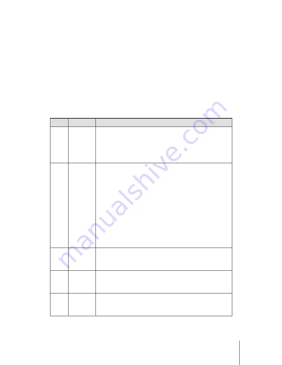
The Keyboard Command Bar supports the following: 


Key 

Option 

Description 

Enter Execute 

Command

The Enter key is used to activate sub-menus when the selected 

feature is a sub-menu, or to display a pick list if a selected option has 

a value field, or to select a sub-field for multi-valued features like 

time and date. If a pick list is displayed, the Enter key will undo the 

pick list, and allow another selection in the parent menu. 

ESC 

Exit 

The ESC key provides a mechanism for backing out of any field. 

This key will undo the pressing of the Enter key. When the ESC key 

is pressed while editing any field or selecting features of a menu, the 

parent menu is re-entered.   

When the ESC key is pressed in any sub-menu, the parent menu is 

re-entered. When the ESC key is pressed in any major menu, the exit 

confirmation window is displayed and the user is asked whether 

changes can be discarded. If “No” is selected and the Enter key is 

pressed, or if the ESC key is pressed, the user is returned to where 

they were before ESC was pressed without affecting any existing 

settings. If “Yes” is selected and the Enter key is pressed, Setup is 

exited and the BIOS continues with POST. 


Select Item 

The up arrow is used to select the previous value in a pick list, or the 

previous options in a menu item's option list. The selected item must 

then be activated by pressing the Enter key. 


Select Item 

The down arrow is used to select the next value in a menu item’s 

option list, or a value field’s pick list. The selected item must then be 

activated by pressing the Enter key. 


Select 

Menu 

The left and right arrow keys are used to move between the major 

menu pages. The keys have no affect if a sub-menu or pick list is 

displayed. 

Содержание Opteron 200 series

Страница 1: ...User Manual for 4U Server Blade Opteron 800MHz Hyper Transport Bus Aug 2005 Revision B P N 1230B0015201...

Страница 2: ...r Permission is granted to display copy distribute and download the materials in this User Manual for personal non commercial use only provided you do not modify the materials and that you retain all...

Страница 3: ...t Corporation Red Hat is a registered trademark and logos are trademarks or registered trademarks of Red Hat Inc in the United States and other countries The information in this document is provided a...

Страница 4: ...2 4 2 3 1 To install the processor 2 5 2 3 2 To install the heat sink 2 6 2 3 3 To remove the processor and heat sink 2 7 2 4 System Memory 2 8 2 4 1 To install a DIMM 2 9 2 4 2 To remove a DIMM 2 9 2...

Страница 5: ...e socket 2 9 Figure 2 13 HDD Location 2 10 Figure 2 14 Locating the HDD to the HDD tray 2 10 Figure 2 15 Installing the HDD 2 11 Figure 2 16 Pressing the HDD release buttons 2 11 Figure 2 17 Lifting t...

Страница 6: ...This chapter provides the safety and regulatory information of Server Blade About This Manual About This Manual...

Страница 7: ...onnel who are qualified in installing configuring maintaining and servicing system hardware and software C Co on nv ve en nt ti io on ns s To make sure that you perform certain tasks properly take not...

Страница 8: ...ture Reference Document Item Description 1 User Manual for 4U Blade Server Chassis Opteron 800MHz Hyper Transport Bus Item Description 1 AMD Opteron 200 series Server Blade 2 PMC Card Option 3 AMD Opt...

Страница 9: ...his equipment generates uses and can radiate radio frequency energy and if not installed and used in accordance with the instructions may cause harmful interference to radio communications Operation o...

Страница 10: ...e the battery Do not expose to temperatures higher than 60 C Do not disassemble crush puncture short external contacts or dispose of in fire or water Replace only with the spare parts designated for t...

Страница 11: ...Product Introduction This chapter describes the general product introduction information of the Server Blade Chapter 1 Product Introduction...

Страница 12: ...tr ro od du uc ct ti io on n This chapter provides the detailed features for battery processor system memory HDD system configuration switch with pictures for your reference AMD Opteron 200 series Se...

Страница 13: ...s on each ATCA processor monitor temperature and voltage alerting system before problems occur The supplier s blades are hot pluggable and can be powered on off and reset remotely The following highli...

Страница 14: ...major component is identified by the number 1 2 1 Opteron 200 series Server Blade Overview Figure 1 2 Opteron 200 series Server Blade Component Locations DIMM Socket 1B System Battery DIMM Socket 1A...

Страница 15: ...Off Green On Link Active Blade Switch LED Off No Link COM Port USB Connector 1 USB Connector 2 Green On Link Active NIC1 Status Off No Link Green On Link Active NIC2 Status Off No Link Green On Active...

Страница 16: ...Hardware Operation This chapter provides step by step instructions for installation and hardware information for this Server Blade Chapter 2 Hardware Operation...

Страница 17: ...ectronics and drives but portions of the power supply and some internal circuitry remain active To completely remove all power from the system disconnect the power cord from the server Power off the S...

Страница 18: ...s and accumulators should not be disposed of together with general household waste Use the public collection system or return used batteries to your authorized partners or their agents for proper recy...

Страница 19: ...ly Figure 2 3 Putting the battery into the holder 2 2 2 To remove the battery Pull the battery retaining clip away from the battery Lift the battery out of the holder Figure 2 4 Pulling the battery ou...

Страница 20: ...re the installation 1 If SINGLE processor is intended always install the processor on the processor 1 socket and for the location of processor 1 and processor 2 please refer to the above figure 2 If i...

Страница 21: ...is shown while making sure that the processor is parallel to the socket Lock the socket by pushing down the lever Figure 2 6 Pressing the locking lever down Notes When the processor is in place press...

Страница 22: ...2 7 Heat Sink and Sponge Location Note Make sure these two heat sinks must be installed as the above pictures shows Please don t mistake the position of them Place the heat sink onto the socket and al...

Страница 23: ...at sink on top of the installed processor please don t forget to check if the grease is complete on bottom of heat sink And follow the instruction 2 3 3 To remove the processor and heat sink Reverse t...

Страница 24: ...are respectively DIMM Socket 1A DIMM Socket 1B for processor 1 DIMM Socket 2A DIMM Socket 2B for processor 2 For the location of each DIMM socket please refer to 1 2 1 Opteron 200 series Server Blade...

Страница 25: ...e DIMM into the socket on the server blade The release button will automatically be locked Figure 2 11 Inserting the DIMM into the socket Caution DIMMs fit in only one direction DO NOT force a DIMM in...

Страница 26: ...t data integrity 2 2 5 5 H HD DD D The location of HDD is shown as below Figure 2 13 HDD Location Important Before you install or remove the HDD please see 2 1 Before You Start 2 5 1 To install the HD...

Страница 27: ...ress down the HDD to make it fit into the two release buttons Figure 2 15 Installing the HDD 2 5 2 To remove the HDD Press the HDD release buttons simultaneously Figure 2 16 Pressing the HDD release b...

Страница 28: ...r remove the PMC card please see 2 1 Before You Start 2 6 1 To install the PMC Card Locate the bezels to the PMC card with the four mounting screws Figure 2 19 Locating the bezels with the screws Care...

Страница 29: ...Hardware Operation 2 13 Securing the PMC card to the blade with four screws Figure 2 21 Securing the PMC card to the blade 2 6 2 To remove the PMC Card Reverse the above steps to remove the PMC Card f...

Страница 30: ...ion of server blade board switch is shown as below Figure 2 22 Server Blade Board Switch Location Switch Function Off On 1 Configuration Data Disable Enable 2 Configuration Data Lock Disable Enable 3...

Страница 31: ...de make sure the power is off To power off the server see 2 1 1 Power Off 2 8 1 To Install and Remove the Server Blade To install server blade Slide the server blade fully into the bay Lock the handle...

Страница 32: ...1230B0015201 Hardware Operation 2 16 Release the handle Grab the handle and slide the single blade server from the blade server enclosure Figure 2 26 Removing the server blade...

Страница 33: ...BIOS Setup Chapter 3 BIOS Setup This chapter provides information about BIOS Setup...

Страница 34: ...BIOS requests that the user reconfigure the system and reboot Note Because the BIOS code is the most often changed part of the motherboard design the BIOS information described in this section may be...

Страница 35: ...ser The Server Setup utility major menus are Main Menu Advanced Menu Boot Menu Security Menu and Exit Menu Options Menu Each Option Menu occupies the left and center sections of the screen Each menu c...

Страница 36: ...out of any field This key will undo the pressing of the Enter key When the ESC key is pressed while editing any field or selecting features of a menu the parent menu is re entered When the ESC key is...

Страница 37: ...us key on the other keyboard but will have the same effect F9 Setup Defaults Pressing F9 causes the following to appear Setup Confirmation Load default configuration now Yes No If Yes is selected and...

Страница 38: ...BIOS Flash Utility ROM image Recovery Mode AMIBOOT ROM ROM image Table 3 3 BIOS Requirements Description 3 4 2 ROM Flash Update under DOS Prompt Copy AFUDOS EXE Autoexec BAT and RomFileName rom ROM im...

Страница 39: ...sk and boot to DOS prompt Run F BAT or FB BAT depend on the flash block F BAT Only Update BMC OP Code FB BAT Update BMC with OP Code and Boot Block Turn off the power button and unplug server blade fr...

Страница 40: ...s file name Key in order dir to check whether the downloading of the files has been finished Key in the order update mgmt blade bmc file name e g t img Key in which chassis management will be updated...

Страница 41: ...Diagnostic Tool Chapter 4 Diagnostic Tool This chapter provides information about the Diagnostic Tool...

Страница 42: ...failures or non fatal error conditions View events in the IPMI event log from the BIOS setup BIOS Setup A utility used to report memory CPU and system settings Stores settings information in nonvolati...

Отзывы: