background image

www.amcelettronica.com

Installation Instructions

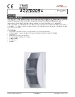
soutdoor L

R1

R2

TAMPER

ALARM

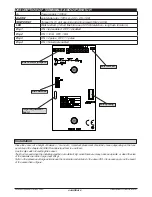
EOL terminal

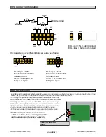
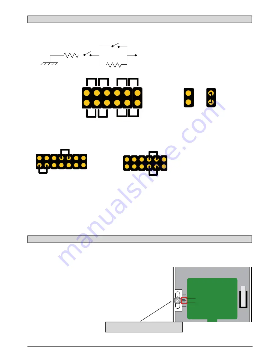
It is possible to have different balaced value, see figure:

R1 tamper = 10K

R2 alarm contact =4K7

Not alarm=10K

Alarm = 14K7 (R1+R2)

Tamper = Open

R1 tamper = 5K6

R2 alarm contact =5K6

Not alarm=5K6

Alarm = 11K2 (R1+R2)

Tamper = Open

close

open

8K2

8K2

5K6

5K6

4K7

4K7

1K

2K2

R1

R2

5K6

5K6

4K7

10K

EOL open = N.C. alarm contact

EOL close  = balanced enabled

Board Adjustment 

In addition to the electronic adjustments, the sensor can be vertically adjusted physically regarding the direction of the 

beams. As you can see in the picture below you can slide the board inside the cover.

1 2 3 4 5 6

FUNCTIONS

Sliding system detail

board

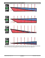
The sliding is opposite to the beam so when the board is moved up-

ward the beams are lowered and when it is lowered beams are raised. 

In the figures below you can see the effect achieved when moving 

the board. These adjustments are also needed for animal tolerance. 

With the lens mounted by default (volumetric up, horizontal curtain 

down) you can get a very accurate result on animal tolerance.

Test the sensor alarm threshold whenever an adjustment is made.

NOTE: sliding the board it must remain 

/ - 2 mm. from centrally located for 

not to compromise the sensor detection

EOL jumper configuration

Содержание soutdoor L

Страница 1: ...centage of false alarms With hight thermal variations the totally digital temperature compensation system guarantees a great performance Has 15mt coverage with angle of 90 With usable different type o...

Страница 2: ...ed Dip switches EOL resistor jumpers Walk test LED anti opening height adjustment board Installation Place the sensor at a height of between 1 m and 2m Important placement should be chosen depending o...

Страница 3: ...ing the direction of the beams As you can see in the picture below you can slide the board inside the cover FUNCTIONS Sliding system detail board The sliding is opposite to the beam so when the board...

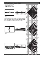
Страница 4: ...UNCTIONS 1 2 3 4 5 6 FUNCTIONS 1 2 3 4 5 6 FUNCTIONS Coverage diagrams based on board position Note the figures show the effect of the beams based on the position of the board Since they are purely in...

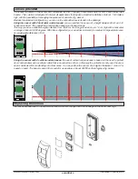
Страница 5: ...ackage there are 3 types of lenses Horizontal curtain lens Fig 1 Vertical curtain lens fig 2 Volumetric curtain lens fig 3 On the sensors are mounted by default on the PIR1 top the volumet ric lens an...

Страница 6: ...the beam range This way you have a variable height protection from 35 40 cm from the ground and up to 1 6 cm high with a horizontal coverage of about 80 100 degrees With this configuration you can ac...

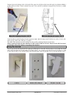
Страница 7: ...be positioned towards the outside Important the volumetric lens has one direction therefore pay close attention to how it is positioned When put up against the light you can see how the FRESNEL lenses...

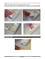
Страница 8: ...nt the positioning mentioned previously Note remember that the distance between the board and the base is 13 5 mm Space reserved for the proper positioning of the cable feeder or any piping to be inse...

Страница 9: ...he manufacturer shall not be responsible if the product is tampered with by unauthorised persons We recommend that you check the correct operation of the alarm system at least once per month A reliabl...

Отзывы: