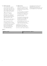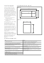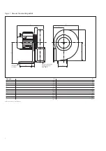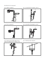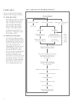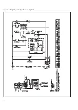
Figure 11 Logic sequence for Herringbone control panel
6 Control system
The control system must be installed in
accordance with the design specification.
6.1 Control panel design
Ambi-Rad control panels are available
either as standard units to control
single or multiple zones of heaters
utilising the Ambi-Rad black bulb
radiant thermostat. Special control
functions are available on request.
Herringbone control panels use the
logic in figure 11 to operate in a safe
and satisfactory manner.
6.2 Installation of control panel
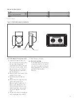
To install the Ambi-Rad control panel
remove the plastic plugs from the four
9mm diameter holes in the back of the
control box. Using these holes fix the
box in a convenient position to a
suitable plugged wall or solid structure
with No. 10 gauge wood screws or
6mm diameter bolts or set screws.
Access to the holes may be gained from
the inside of the box without the
necessity of removing the wiring
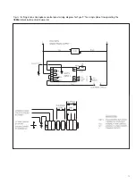
chassis. Make the electrical connections
in accordance with figure 12a or 12b
and cut holes in the removable gland
plate provided in the box. Conduit or
strain relief glands should be used.
Power onto panel
Mode switch in off position
Mode switch in auto position
Mode switch in constant position
(one or all zones)
No heaters on
Time clock off
Time clock on
Break contacts 8 & 9 on
Make contacts 8 & 9 on
black bulb controller
black bulb controller (via relay or
time clock contacts for each zone
Control on night temperature
Control on day
setting for frost protection
temperature setting
Call for heat by black bulb controller
controlling each zone or all heaters
Delay start of Herringbone fan for 30 seconds
to ensure vacuum switch on heaters is
broken (only required for 2 zones or
more on one fan)
Switch on the power suuply to the
Herringbone fan and power supply to
heaters simultaneous
Individual heater vacuum switch senses combustion vacuum
Individual heaters start ignition sequences
Zone control switches off
Other zones carry on firing (if fitted)
Zone control calls for heat
Power off to all heaters or zones
and to stop Herringbone fan
(Possible
alternative
control
function to
override
temperature
controller)
11
Содержание Herringbone HB
Страница 1: ...HERRINGBONE HB COMBINED FLUE SYSTEM...
Страница 14: ...Figure 12b Wiring diagram for Type 0 fan single phase 13...


