background image


Cleaning, maintenance and repairs 


ZG-B

 BAG0170.2  02.21 

93 


10.8 

Hydraulic fluid filter 

The oil filter (

Fehler! Verweisquelle konnte 

nicht gefunden werden.

/1) with its contamina-

tion indicator (

Fehler! Verweisquelle konnte 

nicht gefunden werden.

/2) monitors the contam-

ination of the hydraulic oil. 


Fig. 60


Check the contamination indicator 

regularly to ensure proper function 

of the hydraulic system and its 

components. 


Replace the oil filter immediately if 

a red ring is visible instead of the 

green ring.  

    After replacing the oil filter, press 

the contamination indicator back 

down. 


 The green ring is visible again. 


CAUTION 
Danger of injuries from escaping 

hydraulic oil at high pressure! 

Work on the hydraulic system only in a 

depressurized state. 


10.9 

Cleaning the solenoid valves 

To eliminate impurities from the solenoid valves, 

they must be flushed through. This may be nec-

essary if deposit prevent the slider fully opening 

or closing. 
  1.  Unscrew the magnetic cap (Fig. 61/1) 
  2.  Remove the solenoid (Fig. 61/2) 
  3.  Unscrew the valve rod (Fig. 61/3) with valve 

seats and clean with compressed air or hy-

draulic fluid.


Fig. 61 


CAUTION 
Danger of injuries from escaping 

hydraulic oil at high pressure! 

Work on the hydraulic system only in a 

depressurized state.! 


Содержание ZG-B 8200 Truck

Страница 1: ...Operating Manual az ZG B 8200 Truck Pack top spreader MG5979 BAG0170 2 02 21 Printed in Germany Please read this operating manual before first commis sioning Keep it in a safe place for future use en ...

Страница 2: ...tself The person in question would not only harm himself but also make the mistake of blaming the machine for pos sible failures instead of himself In order to ensure success one should enter the mind of a thing make himself familiar with every part of the ma chine and get acquainted with how it s handled Only in this way could you be satisfied both with the machine and with yourself This goal is ...

Страница 3: ...N WERKE H DREYER GmbH Co KG Postfach 51 D 49202 Tel E mail Hasbergen 49 0 5405 501 0 amazone amazone de Spare part orders Spare parts lists are freely accessible in the spare parts portal at www amazone de Please send orders to your AMAZONE dealer Formalities of the operating manual Document number MG5979 Compilation date 02 21 Copyright AMAZONEN WERKE H DREYER GmbH Co KG 2021 All rights reserved ...

Страница 4: ...man ual and particularly the safety information Only after careful reading will you be able to benefit from the full scope of your newly purchased machine Please ensure that all the machine operators have read this operating manual before commissioning the machine Should you have any questions or problems please consult this op erating manual or contact your local service partner Regular maintenan...

Страница 5: ...working 22 2 16 Safety information for the operator 23 2 16 1 General safety and accident prevention information 23 2 16 2 Hydraulic system 24 2 16 3 Electrical system 24 2 16 4 Fertiliser spreader operation 25 2 16 5 Universal joint shaft operation 26 2 16 6 Cleaning maintenance and repairs 26 3 Mounting on a carrier vehicle 27 3 1 Loading with a lifting crane mounting the spreader on the carrier...

Страница 6: ...vane positions 62 6 3 3 Checking the working width with the mobile test rig optional 64 6 3 4 Late top dressing 65 6 3 5 Setting the funnel chute 65 6 4 Boundary ditch and side spreading 66 6 4 1 Boundary and side spreading using the Limiter ZG B boundary spread deflector 67 7 Transportation 70 8 Use of the machine 71 8 1 Filling the machine 73 8 2 Emptying the machine while stationary 74 8 3 Spre...

Страница 7: ...Table of Contents ZG B BAG0170 2 02 21 7 10 11 Screw tightening torques 95 11 Hydraulic diagram 96 ...

Страница 8: ...in the operating manual are always seen from the direction of travel 1 3 Diagrams used Operator control action and responses Actions to be carried out by the operator are given as a numbered list It is important that the sequence of steps is observed The responses for each operator control action are given by an arrow Example 1 Operator control action step 1 Machine response to operator control ac...

Страница 9: ...ulations Have been trained in working with on the machine Have read and understood this operating manual The operator is obliged To keep all the warning symbols on the machine in a legible state To replace damaged warning symbols Obligations of the user Before starting work anyone charged with working with on the ma chine is obliged To comply with the basic workplace safety instructions and acci d...

Страница 10: ...icable These shall be available to the operator at the latest on the comple tion of the contract Guarantee and liability claims for damage to peo ple or goods will be excluded if they can be traced back to one or more of the following causes Improper use of the machine Improper installation commissioning operation and mainte nance of the machine Operation of the machine with defective safety equip...

Страница 11: ... diate death or serious physical injury WARNING Indicates a medium risk which could result in death or serious physical injury if not avoided If the instructions are not followed then this may result in death or serious physical injury CAUTION Indicates a low risk which could cause minor or medium level physical injury or damage to property if not avoided IMPORTANT Indicates an obligation to speci...

Страница 12: ... the operator and mainte nance personnel Check all the available safety equipment regularly 2 4 Safety and protection equipment Before each commissioning of the machine all the safety and protec tion equipment must be properly attached and fully functional Check all the safety and protection equipment regularly Faulty safety equipment Faulty or disassembled safety and protection equipment can lead...

Страница 13: ...r behaviour have been trained if necessary and have been in formed about the necessary protective equipment and measures 3 People with specialist technical training shall be considered as a specialist Due to their specialist training and their knowledge of the appropriate regulations they can evaluate the work with which they have been charged and detect possible dangers Comment A qualification eq...

Страница 14: ...r Wartungsarbeiten Sicherheitseinrichtungen auf Funktion überprüfen 2 10 Design changes You may make no changes expansions or modifications to the ma chine without the approval of AMAZONEN WERKE This is also valid when welding support parts Any expansion or modification work shall require the written approval of AMAZONEN WERKE Only use the modification and accessory parts released by AMAZONEN WERK...

Страница 15: ...e parts from third parties does not guarantee that they have been con structed in a way as to meet the requirements placed on them AMAZONEN WERKE shall accept no liability for damage caused by the use of unreleased spare and wear parts or auxiliary materials 2 11 Cleaning and disposal Handle and dispose of any materials used carefully in particular When carrying out work on lubrication systems and...

Страница 16: ...ol consists of two fields Field 1 is a symbol describing the danger surrounded by triangular safety symbol Field 2 is a symbol showing how to avoid the danger Warning symbols explanation The column Order number and explanation provides an explanation of the neighbouring warning symbol The description of the warning symbols is always the same and specifies in the following order 1 A description of ...

Страница 17: ...General safety instructions ZG B BAG0170 2 02 21 17 2 13 1 Positions of warning symbols and other labels The following diagrams show the arrangement of the warning symbols on the machine Fig 1 Fig 2 ...

Страница 18: ...including loss of body parts such as the hand or arm Never open or remove protective equipment from chains or belt drives while the tractor engine is running and the PTO shaft is connected hydraulic drive is engaged or the ground wheel drive is moving MD 078 Risk of crushing fingers or hands by acces sible moving machine parts This danger causes serious injuries including loss of body parts such a...

Страница 19: ...s long as the tractor engine is running with the PTO shaft connected hydraulic drive engaged or as long as the tractor engine can be unin tentionally started with the PTO shaft con nected hydraulic drive engaged MD 095 Read and follow the operating manual and safety information before starting up the machine MD 096 Danger from escaping high pressure hydrau lic fluid due to leaking hydraulic hose l...

Страница 20: ...istance and stay outside the danger area MD 100 This symbol indicates anchorage points for fas tening slinging gear when loading the machine MD 114 This symbol indicates a lubrication point MD116 Nominal speed 540 rpm and direction of rota tion of the machine side drive shaft MD 117 Nominal speed 720 rpm and direction of rota tion of the machine side drive shaft ...

Страница 21: ...uries any where on the body Secure the machine against unintended contin ued movement before uncoupling the machine from the tractor To do this use the parking brake and or the wheel chock s MD 199 The maximum operating pressure of the hydrau lic system is 210 bars MD205 Nominal speed 1000 rpm and direction of rota tion of the machine side drive shaft ...

Страница 22: ...gh non secured working areas Failure of important machine functions Failure of prescribed methods of maintenance and repair Danger to people through mechanical and chemical impacts Risk to environment through leakage of hydraulic fluid 2 15 Safety conscious working Besides the safety information in this operating manual the national general workplace safety and accident prevention regulations are ...

Страница 23: ...weather conditions the driving characteristics of the tractor and the connected machine Use of the machine Before starting work ensure that you understand all the equip ment and actuation elements of the machine and their function There is no time for this when the machine is already in opera tion Do not wear loose fitting clothing Loose clothing increases the risk over being caught by drive shaft...

Страница 24: ...cal system When working on the electrical system always disconnect the battery negative terminal Only use the prescribed fuses If fuses are used that are too highly rated the electrical system will be destroyed risk of fire Ensure that the battery is connected correctly firstly connect the positive terminal and then connect the negative terminal When disconnecting the battery disconnect the negati...

Страница 25: ...eader Do not walk or stand close to rotating spreading discs Do not place any foreign objects in the hopper While carrying out the spread rate check beware of danger points from rotating machine parts For side spreading at field edges bodies of water or roads use side spreading devices Before each use ensure that the attachment parts are properly fitted particularly those for attaching the spreadi...

Страница 26: ...nce and repairs Only carry out maintenance repair and cleaning work on the machine when The drive is switched off The ignition key has been removed The machine connector has been removed from the on board computer Regularly check the nuts and bolts for a firm seat and retighten them as necessary Secure the raised machine and or raised machine parts against unintentional falling before maintaining ...

Страница 27: ...Fig 3 There are 2 attachment points respectively at the front Fig 3 1 and rear Fig 3 2 in the hopper DANGER When loading the implement with a lifting crane the marked at tachment points for slings must be used DANGER The minimum tensile strength per sling must be 1000 kg Fig 4 Manoeuvring equipment drawbar jack and running gear can be sent back and then reimbursed ...

Страница 28: ...nect with the implement plug Observe that the maximum load capacity of the frame is 12000 kg To mount the ZG TRUCK on the carrier vehicle use the mount ing plates under the frame and the mounting straps at the front on the frame Use adequately dimensioned connecting elements when mount ing the ZG TRUCK on the carrier vehicle ο Mounting plate bolted connection At least 4x M 20 bolts respectively ο ...

Страница 29: ...Mounting on a carrier vehicle ZG B BAG0170 2 02 21 29 3 2 Mounting dimensions Spreading disc height ...

Страница 30: ...Mounting on a carrier vehicle 30 ZG B BAG0170 2 02 21 1 Mounting plates for M20 bolted connection 2 Mounting straps for pins with 40 mm diameter ...

Страница 31: ...er or code letter have been applied to the gripping sections in order to assign the respective hydraulic function to the pressure line of a control unit Films are stuck on the implement for the markings that illustrate the respective hydraulic function The control unit must be used in different types of activation depending on the hydraulic function Latched for a permanent oil circulation Tentativ...

Страница 32: ...ing WARNING For the oil return use only DN16 lines and select short return paths Pressurise the hydraulic system only when the free return has been correctly coupled Install the coupling union supplied on the pressure free oil return flow Implement side connections in compliance with ISO15657 1 P feed line pressure line plug standard width 20 2 LS control line plug standard width 10 3 T return lin...

Страница 33: ...0 2 02 21 33 4 Product description 4 1 Overview of subassemblies Fig 5 1 Frame 2 Belt conveyor 3 Hopper 4 Guard tube 5 Spreader unit with spreading discs 6 Gearbox 7 Swivelable hopper cover Option 8 Main shutter Double shutter Option ...

Страница 34: ...disc If the spreading disc is positioned at a height of 1500 mm the guard tube must be installed underneath the spreading disc Fig 6 4 3 Transportation equipment Fig 7 1 2 rear lights 2 2 red reflectors triangular 3 1 registration plate holder with lighting Fig 7 Fig 8 1 2 x 3 reflectors yellow lateral view distance of max 3m Fig 8 ...

Страница 35: ...e contours Direction of travel to the left 15 Direction of travel to the right 15 Along the gradient Up the slope 15 Down the slope 15 Using the steering drawbar with TrailTron control for precise tracking is prohibited if on sloping terrain See page 72 The intended use also includes Compliance with all the instructions in this operating manual Execution of inspection and maintenance work Exclusiv...

Страница 36: ...iate section shall be valid No one may stand in the machine danger area as long as the engine is running with a connected hydraulic system The operating person may only move the machine or switch or drive the tools from the transport position to the working position or vice versa when there is no one in the machine danger area Danger points exist In the area of moving parts ο Rotating spreading di...

Страница 37: ...nding on equipment 540 min 1 720 min 1 1000 min 1 Gear ratio PTO shaft speed Spreading disc speed 1 1 33 1 1 1 0 72 4 7 1 Weights basic machine and modules Basic machine 1345 kg Charging sieves 75 kg Swivelable hopper cover 80 kg 4 8 Noise production data The workplace related emission value acoustic pressure level is 74 dB A measured in operating condition at the ear of the tractor driver with th...

Страница 38: ...ce The conveyor belt Fig 10 1 delivers the spreading material Fig 10 2 from the hopper Fig 10 3 to the spreader units The spreading discs Fig 10 4 are driven by the PTO shaft with 540 rpm 720 rpm or 1000 rpm The freely adjustable hopper outlet determines the amount of material entering the spreading unit and thus the amount of material to be spread The spreader units distribute the spreading mater...

Страница 39: ...in shutter slide Fig 11 1 Main shutter slide 2 Hand lever for adjustment 3 Clamping bolt to secure adjustment 4 Scale 5 Pointer Adjust the quantity to be spread on the main shutter slide Close the main shutter slide or double shutter during the transport ...

Страница 40: ...t for 17 mm wrench Open and close hydraulically the fertilizer sluice via double shutter By half side opening half side spreading is possible Fig 13 1 Double shutter taken out of operation Commissioning decommissioning workshop task 1 Removing the R clip 2 Move the double shutter into the completely lowered raised position via the spindle using a power screwdriver 3 Secure the position using R cli...

Страница 41: ...eft and right side and secure with a linch pin Removal pull out the linch pins and remove the chain rake from the mount Fig 14 5 3 2 Chain rake on the double shutter Implements with a double shutter can be equipped with a chain rake mounted on the dou ble shutter Put the chain rake into operating position work shop task 1 Take the double shutter out of operation 2 Remove each of the chain ends fro...

Страница 42: ...ucture and function 42 ZG B BAG0170 2 02 21 Take the chain rake out of operation workshop task 1 Put the chain hook in the parking device on the double shutter 2 Put the double slider into operation Fig 16 ...

Страница 43: ... 16 m The OM spreading discs 18 24 can be used for working widths of 18 24 m The OM spreading discs 24 36 can be used for working widths of 24 36 mr As seen in the direction of travel Left spreading disc Fig 18 1 with L mark Right spreading disc Fig 18 2 with R mark Spreading vane Long Fig 18 3 Adjustment scale with values from 35 to 55 Short Fig 18 4 Adjustment scale with values from 5 to 28 Fig ...

Страница 44: ...cture and function 44 ZG B BAG0170 2 02 21 Setting the funnel chute Fig 19 The holes are labelled with the numbers 1 and 2 Funnel chute position Spread rate Hole 1 up to 150 kg ha Hole 2 More than 150 kg ha ...

Страница 45: ... BAG0170 2 02 21 45 5 5 Spreading lime with lime spreading discs Fig 20 1 spreading discs of lime 2 guide plate For spreading earth moist lime fertilizers use the deflector guide and the chain rake Setting the guide plate Fig 21 ...

Страница 46: ... 5 6 Spreading granulated fertiliser with lime spreading discs Fig 22 1 spreading discs of lime 2 guide plate Special case For spreading granulated non nitrogen fertiliser up to a working width of 18 m use the roof chute Roof chute assembly Fig 23 ...

Страница 47: ... bone meal spreading vanes turn them by hand to make sure that the spreading vanes do not collide Fig 24 1 Spreading discs for bone meal 2 Roof chute For spreading bone meal up to a working width of 18 m use the roof chute and the chain rake 5 8 Spreading disc holder Spreading disc holder Fig 25 1 For carrying two extra spreading discs on the left and right sides of the hopper Fig 25 ...

Страница 48: ...ading using the Limiter Fig 26 Shut down and turn on hydraulically the Limiter To set the values of the setting table position the boundary spread deflector on the guide bracket Fig 26 5 10 Conveyor belt The conveyor belt Fig 27 delivers the spread ing material via the flap control from the hopper to the spreader units Depending on equipment version the conveyor belt is driven on the with hydrauli...

Страница 49: ...lically The belt conveyor is driven hydraulically by a gearbox Fig 28 5 11 Foldable ladder The foldable ladder Fig 29 1 enables a user to comfortably ascend the hopper for cleaning pur poses Fig 29 Warning Keep the ladder folded in and locked when the vehicle is in mo tion Fig 29 2 ...

Страница 50: ...t lime remove the sieve screen Fig 30 The charging sieves can be trodden on in order to clean the inside of the hopper 5 13 Swivelable hopper cover optional The swivellable hopper cover ensures for dry goods to be spread even in event of wet weath er The hopper cover is optional Hydraulically operated ο via tractor control unit natural ο via in cab terminal AMATRON 3 Fig 31 ...

Страница 51: ...ting recom mendations Through the FertiliserService application for Android and iOS mobile devices From the online FertiliserService See www amazone de Service FertiliserService Using the QR codes shown below you can directly access the AMA ZONE website to download the FertiliserService application iOS Android Contact partners in the respective countries 0044 1302 755720 0039 0 39652 100 0036 52 4...

Страница 52: ...tor as an initial value for the calibration factor when calibrating the fertiliser After identification of the fertiliser read the settings from the setting table Shutter position for manual spread rate setting Spreading vane position Boundary and border spreading with the limiter boundary spreading deflector If you cannot definitively assign the fertiliser to a kind listed in the setting chart th...

Страница 53: ... of the conveyer belt The slider position required for a specific spreading quantity is determined by means of fertiliser calibration The hydraulic functions are operated using the AMATRON 3 ο Open and close the slide gates ο Take the Limiter M into and out of ser vice ο Setting the quantity ο Open and close the hopper covers Fig 32 To start up the ZG B the basic data for the rele vant machine typ...

Страница 54: ... ensuring all the hy draulic functions Depending on the equipment the adjustable hydraulic throttles for the hydraulic swivelable hopper cover can be found on the hydraulic block The oil filter is equipped with a maintenance indicator and should be cleaned according to this Fig 34 1 Cover plate of the hydraulic block and ma chine computer 2 Oil filter Fig 34 ...

Страница 55: ...a complete standstill Please note that the individual spreading properties of the spread material have a significant influence on the lateral distribution and spread rate For this reason the listed setting values should only be considered as a reference The spreading properties depend on the following factors The fluctuations in the physical data specific weight grain size frictional resistance cw...

Страница 56: ...ing disc OM 24 36 Working witdh 27m Working speed 12 km h spread rate 200 kg ha 1 For fertiliser or trade name please refer to the setting chart 2 Read off group of fertiliser group 1 ZG B Drive Bulk density 1 03 kg l im terminal AMATRON 3 eingeben ZG B Spezial Super 3 Setting position refer to the setting chart ZG B Super always select 12 km h shutter position 18 belt speed I Fertiliser trade nam...

Страница 57: ...10 12 8 10 12 14 323 258 215 308 246 205 269 215 179 239 191 159 231 185 154 16 369 295 246 351 281 234 308 246 205 273 219 182 211 211 176 18 415 332 277 395 316 264 346 277 231 308 246 205 237 237 198 The value for the shutter position must be halved for the belt speed II It is recommended to carry out a spread rate check with this slider position ...

Страница 58: ...or belt speed II divide the determined shutter position by two 1 Determine the bulk density kg l of the fertiliser by weighing a precisely filled litre gauge 2 On the sliding ruler push the marking K to the desired spreading quantity kg ha A 3 Read the spreading volume C from the bulk density B deter mined 4 On the back of the sliding ruler cover the spreading volume D with the red line 2 and read...

Страница 59: ...termination of the shutter slide position with the aid of the cal culating disc rule is carried out after a spread rate check This way the varying flowing properties of the fertiliser are already considered when determining the shutter slide position The optimum spread pattern requires the maintenance of constant PTO shaft rev speed and operating speed except for ground wheel drive and AMATRON 3 d...

Страница 60: ...according to the setting chart 2 Unscrew the hex bolt 3 Remove the spreading disc 4 Screw in the hex bolt again 5 Remove the funnel chute 6 Hang the calibration device Fig 36 1 in the pockets Fig 36 2 and secure using clip pins Fig 36 3 sichern 7 Hang each one calibration bucket Fig 36 4 on the hook underneath the outlets After a test run which delivers the fertiliser in relation to the shutter sl...

Страница 61: ... The pivotable spreading vanes allow the ad justment of these specific spreading properties of a fertiliser so that the respective fertiliser can be spread over the desired working width Working width Spreading disc pair 10 16 m 18 24 m 24 36 m OM 10 16 OM 18 24 OM 24 36 The primary factors that affect the spreading properties are Granule size Bulk density Surface condition Humidity We therefore r...

Страница 62: ...7 1 with values from 5 to 28 the longer spreading vanes Fig 37 4 are assigned the scale Fig 37 2 with the values from 35 to 55 ο For the short spreading vane Fig 37 3 read off the set value on the read off edge Fig 37 5 ο For the long spreading vane Fig 37 4 read off the set value on the read off edge Fig 37 6 Swivelling the spreading vanes to a higher scale value Fig 37 1 or Fig 37 2 increases th...

Страница 63: ... the respective spreading vane so that you can read off the required setting on the scale on the read off edge 3 5 Firmly retighten the respective wing nut by hand without a tool Extract from setting chart Example Kind of fertiliser KAS 27 N gran Hydro Rostock Spreading disc OM 24 36 Desired workind witdh 27m 1 For fertiliser or trade name please refer to the setting chart 2 Read off group of fert...

Страница 64: ...actors that affect the spreading properties are Granule size Bulk density Surface condition and Humidity The setting values of the setting chart are there fore to be considered guideline values only as the spreading properties of the different types of fertiliser may change We recommend checking the working width of the machine using the mo bile fertiliser test rig Fig 38 Fig 38 See the operating ...

Страница 65: ...p dressing in crops may be conducted For late top dressing Swivel the swivel blades of the spreading discs without slackening the nuts without any tools into the upper position Fig 40 This way the fertiliser spread fan is raised Fig 39 Fig 40 6 3 5 Setting the funnel chute Adjust the funnel chute as follows Fig 41 Funnel chute posi tion Spread rate Hole 1 up to 150 kg ha Hole 2 over 150 kg ha ...

Страница 66: ...ordinance specifies the following No fertiliser must be spread within one me tre of the boundary with use of boundary spreading devices No fertiliser must be spread within three metres of the boundary without use of boundary spreading devic es Erosion and wash away e g in surface waters must be prevented Fig 42 Fig 43 3 Side spreading Fig 44 The boundary is delineated by an area in agricul tural u...

Страница 67: ...from the setting chart The values of the setting chart are to be understood as guide numbers as the fertiliser conditions may vary Readjust the Lim iter if necessary The boundary edge distance in the setting chart always indi cates half the working width Fig 45 Boundary edge distance half working width corresponding to the mounted OM spreading discs Boundary spreading Edge spreading Ditch spreadin...

Страница 68: ...ttings For setting the numerical values move the boundary spreading de flector on the guide bar 1 Release the clamping lever for this purpose If the swivel range of the clamping lever handle is not sufficient lift the handle turn back and lower again 2 Push the boundary spreading deflector on the guide bar until the indicator is positioned at the value to be set from the setting chart 3 Tighten th...

Страница 69: ...lower the border spread deflector hydraulically On the upper side of the border spread deflector you will find on the right hand and left hand side each one setting lock Fig 49 1 Slacken the nuts Fig 49 1 of the setting locks 2 Manually raise the deflector 3 Position the setting locks up Fig 49 2 to the stop and firmly tighten the locks 4 Lower the deflector Fig 48 Fig 49 ...

Страница 70: ...e machine against unintentional movements before starting transportation WARNING Danger of injury for persons standing in the vicinity of the ma chine due to unintentional start up of the implement Switch off the control terminal before road transport CAUTION Use transport locking for locking the raised ladder to prevent it from folding down again accidentally Close the slider for road travel Clos...

Страница 71: ...anger area of the driven PTO shaft Whenever the machine is used first check to ensure that the safety devices and guards of the PTO shaft are fully intact and functional Have damaged safety devices and guards of the PTO shaft re placed immediately by a specialised workshop Check that the PTO shaft guard is secured against rotation by the supporting chain Maintain a sufficient safety clearance betw...

Страница 72: ...e of fertiliser is not known exactly check the working width using the mobile fertiliser test rig When spreading mixed fertilisers note the following ο Each variety may have different flight characteristics ο The individual varieties may separate After ever use remove any fertiliser clinging to the spreading vanes Before starting with the spreading operation Job data Machine data Enter on AMATRON ...

Страница 73: ...clip pins Fig 50 2 8 1 Filling the machine WARNING Danger of breaking during operation insufficient stability and insufficient tractor steering and braking power on improper use of the tractor Comply with the maximum load of the connected machine and the approved axle and drawbar loads of the tractor If necessary drive only with a partially filled hopper Remove residues or foreign bodies from the ...

Страница 74: ...lide gate 2 Remove the spreading discs 3 Refit the spreading disc screws to protect the screw thread 4 Hopper emptying via the PTO shaft drive CAUTION Remove the spreading discs Danger of injury from PTO shaft driven spreading discs CAUTION Do not step on the running floor belt emptying any residues Risk of tripping See the software AMABUS operating manual machine data ...

Страница 75: ...strips Spreading disc OM WARNING Danger of ejection of parts of the spreading vanes swivel blades caused by worn spreading vanes swivel blades Every day at the start and end of spreading work check all spreading vanes for visible damage defects Refer to the criteria for the re placement of wearing parts in the chapter Replacing spreading vanes page 85 WARNING Danger from materials or foreign objec...

Страница 76: ...nished the spreading operation ο Disengage the PTO shaft at slow tractor s rev speed ο Close the shutter GEFAHR Do not stand in the slewing range of the drive wheel and its op erating mechanism Ensure that there are no persons in the danger zone Never reach inside the machine while parts may still be moving Risk of injury Ensure that the PTO shaft rev speed is matched with the spreader unit Set th...

Страница 77: ...lands the fol lowing must be noted Open and close the sliders for forward tramlines T1 T2 etc and return trips tramlines T3 etc at different distances to the field edge Open the slide gate after entering the tram line at point P1 Fig 52 when the spreader discs are at distance X from the tramline of the headland ο X 1 working width with working widths 18m ο X 1 5 working widths with working widths ...

Страница 78: ...g discs and the spreading vanes Clean the spreading discs and the spreading vanes The spreading properties of your fertiliser differ from those of the one we tested when creating the setting chart Contact the AMAZONE Fertiliser Service 05405 501 111 Spreader unit measurements are incorrect Check the measurements of the spreader unit and correct if nec essary Too much fertiliser in the tractor trac...

Страница 79: ...ctions Fluid supply at the tractor is not switched on Switch on fluid supply at the trac tor Power supply to valve block inter rupted Check cable plug and contacts Oil filter contaminated Replace clean oil filter Seite 93 Solenoid valve dirty Rinse solenoid valve sivulla 93 Overheating of the tractor hy draulic fluid System converting bolt on the hydraulic block is incorrectly set Fluid quantity n...

Страница 80: ...s also affect parts that come into contact with these lubricants Do not exceed a greasing pressure of 400 bar when greasing with high pressure grease guns The following are prohibited ο drilling the running gear ο drilling through existing holes on the transport frame ο welding load bearing components Protective measures are necessary such as covering lines or extending lines in particularly criti...

Страница 81: ...pecially carefully Treat dry machine with an anticorrosive agent Only use biologi cally degradable protective agents Cleaning with a pressure washer steam jet Always observe the following points when using a pressure washer steam jet for cleaning ο Do not clean any electrical components ο Do not clean any chromed components ο Never aim the cleaning jet of the cleaning nozzle of the high pressure c...

Страница 82: ...ation points and grease gun before greasing so that no dirt enters the bearing Completely press out the soiled grease in the bearings and replace it with new grease Fig 53 Lubricants For lubrication use a lithium saponified multipurpose grease with EP additives Company Lubricant designation Normal use conditions Extreme use conditions ARAL Aralub HL 2 Aralub HLP 2 FINA Marson L2 Marson EPL 2 ESSO ...

Страница 83: ...ee page Workshop work Spreading discs and vanes Condition check replace if nec essary 85 Oil filter Check contamination indicator replace oil filter if necessary Hydraulic system Check for defective hose lines 93 X Monthly every 50 operating hours Component Maintenance work see page Workshop work Hydraulic system Check for leak tightness 89 X As necessary Component Maintenance work see page Worksh...

Страница 84: ...y L left R right Beforehand remove the funnel chute if fitted The right hand side gearbox shaft is provided with a shear pin Here always set up the right hand spreading disc with the two keys GEFAHR Do not stand in the immediate vicinity of the rotating spreading discs Do not touch any of the machine s moving parts Wait until they have come to a complete standstill Before changing the spreading di...

Страница 85: ...e uninten tional release of fixing bolts and quick release screw connec tions When replacing the spreading vanes it is essential to replace used self locking nuts of the fixing bolts with new ones A used self locking nut no longer has the required clamping force to produce a secure screw connection Ensure that the open side of the disc spring is toward the spreading disc before tightening the wing...

Страница 86: ... a fixing bolt washer and an unused self locking nut so that they can move on the spreading disc 7 Tighten the self locking nut with a tool to the extent that you can still just swivel the spreading vane by hand 8 Install the respective quick release bolted connection consisting of a round headed screw plate spring and wing nut Ensure that the open side of the spring plate is pointing towards the ...

Страница 87: ...ecified tightening torque is sufficient 1 Self locking nut 2 Plate spring 3 Fixing bolt 4 Plastic disc 1 Release the self locking nut 2 Remove the self locking nuts disc springs and swivel blades from the fixing bolts 3 Ensure that the plastic disc remains on the fixing pin 4 Apply the assembly paste KA059 to the screw threads 5 Mount the new swivel blade 5 1 Push the new swivel blade on to the fi...

Страница 88: ...is move ment Consequently this causes the pulley to turn around the swivel axle As a result the dis tance between the pulley and the drive drum increases on the side toward which the belt con veyor is moving The larger distance causes the belt conveyor to return to the middle and continue to settle down in the middle Fig 57 Tensioning the belt conveyor The belt conveyor is tensioned with pretensio...

Страница 89: ...ulic hose lines using your hand or fingers Escaping high pressure fluid hydraulic fluid may pass through the skin and ingress into the body causing serious injuries If you are injured by hydraulic fluid contact a doctor immediate ly Risk of infection WARNING Danger of unintentional contact with hydraulic fluid Please take the following first aid measures Following inhalation ο No special action re...

Страница 90: ... storage time of maximum two years Even with proper storage and approved use hoses and hose connec tions are subject to natural ageing thus limiting the length of use However it may be possible to specify the length of use from experience values in particular when taking the risk poten tial into account In the case of hoses and hose connections made from thermoplastics other guide values may be de...

Страница 91: ...riteria Damage to the outer layer up to the ply e g scouring points cuts cracks Brittleness of the outer layer crack formation of the hose materi al Deformations which do not match the natural shape of the hose Both in a depressurised and pressurised state or when bent e g layer separation bubble formation pinching bends Leak points Installation requirements not complied with Life span of 6 years ...

Страница 92: ...re hydraulic hose lines using protective co vers Cover sharp edged components ο The approved bending radii may not be exceeded When connecting a hydraulic hose line to moving parts the hose length must be appropriate so that the smallest approved bend ing radius is not undershot over the whole area of movement and or the hydraulic hose line is not overtensioned Fix the hydraulic hose lines at the ...

Страница 93: ... oil filter press the contamination indicator back down The green ring is visible again CAUTION Danger of injuries from escaping hydraulic oil at high pressure Work on the hydraulic system only in a depressurized state 10 9 Cleaning the solenoid valves To eliminate impurities from the solenoid valves they must be flushed through This may be nec essary if deposit prevent the slider fully opening or...

Страница 94: ...maintenance and repairs 94 ZG B BAG0170 2 02 21 10 10 Gearbox Gear oil 090 l SAE There is no need to change the oil Fill levels ο Conveyor belt gearbox with hydr drive 1 0l ο Universal spreader unit gearbox 2 5l ...

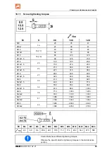
Страница 95: ...25 315 380 M 18 27 290 405 485 M 18x1 5 325 460 550 M 20 30 410 580 690 M 20x1 5 460 640 770 M 22 32 550 780 930 M 22x1 5 610 860 1050 M 24 36 710 1000 1200 M 24x2 780 1100 1300 M 27 41 1050 1500 1800 M 27x2 1150 1600 1950 M 30 46 1450 2000 2400 M 30x2 1600 2250 2700 M M4 M5 M6 M8 M10 M12 M14 M16 M18 M20 M22 M24 2 4 4 9 8 4 20 6 40 7 70 5 112 174 242 342 470 589 Coated bolts have different tighten...

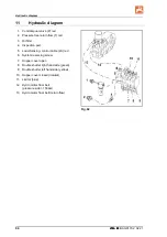
Страница 96: ... Oil filter 4 Inspection port 5 Load Sensing control cable LS red 6 System reversing screw 7 Hopper cover open 8 Double shutter right hand side green 9 Double shutter left hand side yellow 10 Hopper cover closed natural 11 Limiter blue 12 Hydro motor floor belt pressure side 150bar 13 Hydro motor floor belt return flow Fig 62 ...

Страница 97: ...Hydraulic diagram ZG B BAG0170 2 02 21 97 ...

Страница 98: ......

Отзывы: