Operating manual
az
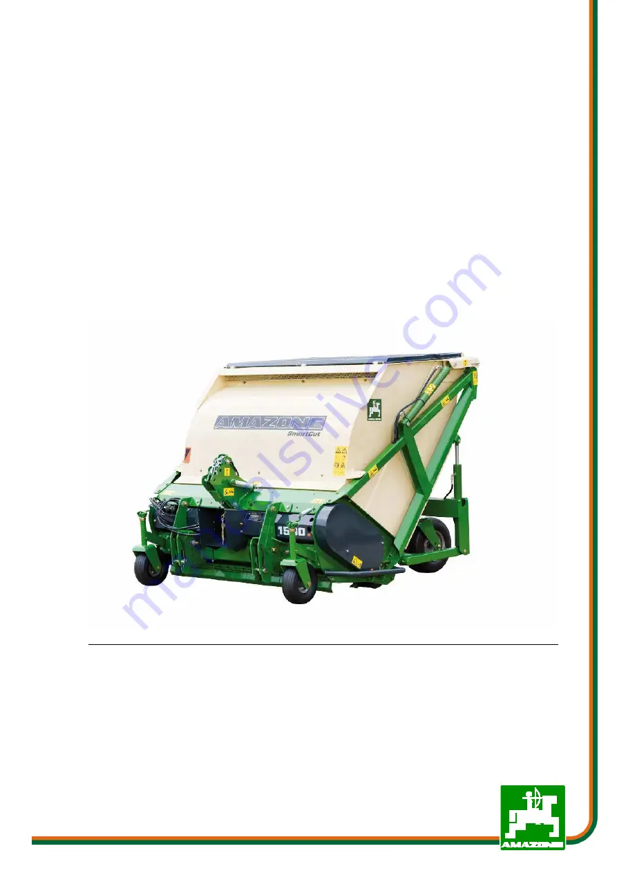
GROUNDKEEPER
GHL, GHL-T SMARTCUT
MG5075 BAF0006.2 05.17 Printed in France
Please read and follow this op-
erating manual before putting
the machine into operation.
Keep it in a safe place for future
use.
en
Страница 1: ...anual az GROUNDKEEPER GHL GHL T SMARTCUT MG5075 BAF0006 2 05 17 Printed in France Please read and follow this op erating manual before putting the machine into operation Keep it in a safe place for fu...
Страница 2: ...itself The person concerned would not only harm himself but also make the mistake of blaming the machine for the reason of a possible failure instead of himself In order to ensure good success one sh...
Страница 3: ...kg Manufacturer s address AMAZONE S A FORBACH 17 rue de la Verrerie BP 90106 F 57602 Phone Fax E mail Forbach France 33 0 3 87 84 65 70 33 0 3 87 84 65 71 forbach amazone fr Spare part orders Spare p...
Страница 4: ...ine into operation Only after careful reading will you be able to benefit from the full scope of your newly purchased machine Please ensure that all the machine operators have read this operating manu...
Страница 5: ...s if the safety information is not observed 25 2 15 Safety conscious working 25 2 16 Safety information for users 26 2 16 1 General safety and accident prevention information 26 2 16 2 Hydraulic syste...
Страница 6: ...56 10 Additional operating instructions for the towed AMAZONE GHL T Lift Groundkeeper 57 10 1 Attaching and detaching the machine 57 10 1 1 Hydraulic connections 57 10 1 2 Three point attachment 58 10...
Страница 7: ...specified in the operating manual are always viewed in the direction of travel 1 3 Diagrams used Instructions for action and reactions Tasks to be carried out by the user are presented as numbered in...
Страница 8: ...gible state To replace damaged warning symbols If you still have queries please contact the manufacturer Obligations of the user Before starting work anyone charged with working with on the ma chine i...
Страница 9: ...able These shall be available to the operator at the latest on the comple tion of the contract Guarantee and liability claims for damage to peo ple or goods will be excluded if they can be traced back...
Страница 10: ...sult in imme diate death or serious physical injury WARNING Indicates a medium risk which could result in death or extreme ly serious physical injury if not avoided If the instructions are not followe...
Страница 11: ...ment regularly 2 4 Safety and protection equipment Before each commissioning of the machine all the safety and protec tion equipment must be properly attached and fully functional Check all the safety...
Страница 12: ...ompany 2 Instructed persons are those who have been instructed in their assigned tasks and in the possible risks in the case of improper behaviour have been trained if necessary and have been in forme...
Страница 13: ...when carrying out replacement work Check all the screw connections for a firm seat On completing maintenance work check the function of safety and protection equip ment 2 10 Constructive changes You...
Страница 14: ...and spare parts from third parties there is no guarantee that they have been designed and manufactured in such a way as to meet the requirements placed on them AMAZONEN WERKE accepts no liability for...
Страница 15: ...rning symbol consists of two fields Field 1 is a symbol describing the danger surrounded by triangular safety symbol Field 2 is a symbol showing how to avoid the danger Warning symbols explanation The...
Страница 16: ...ody from hands or arms Never open or remove protective equipment from chains or belt drives while the tractor engine is running and the PTO shaft is connected hydraulic drive is engaged or the ground...
Страница 17: ...ic locking device MD 086 Risk of any part of the body being crushed beneath raised machine parts if they descend unintentionally This hazard can cause serious injuries to any part of the body or even...
Страница 18: ...loads machine parts Direct persons out of the danger area created by suspended loads machine parts MD 095 Read and understand the operating manual safe ty information before starting up the machine MD...
Страница 19: ...system only from the designated workstation never from a location in the stroke ar ea between tractor and machine MD 100 This symbol indicates lashing points for fastening slinging gear when loading...
Страница 20: ...ially fatal injuries Maintain an adequate safety distance from moving machine parts while the tractor en gine is running Ensure that persons present maintain a sufficient safety distance from moving m...
Страница 21: ...s This danger causes extremely serious injuries with the loss of body parts such as fingers or hands Never open or remove guard devices from rotat ing sharp edged machine parts while the tractor engin...
Страница 22: ...ed as a result of standing in the tipping area when the loading bed has been raised This hazard can cause extremely serious and potentially fatal injuries It is prohibited to stand in the tipping area...
Страница 23: ...2 05 17 23 2 13 1 Positioning of warning symbols and other labels Warning symbols The following diagrams show the arrangement of the warning symbols on the machine MD087 MD170 MD078 MD075 MD123 MD100...
Страница 24: ...General safety instructions 24 Groundkeeper GHL GHL T SMARTCUT BAF0006 2 05 17 MD123 MD100 MD171 MD081 MD078 MD078 MD145 MD079 MD100 MD118 MD097 MD078 MD087 MD076 MD104 MD170 MD078 MD075...
Страница 25: ...eople through non secured working areas Failure of important machine functions Failure of prescribed methods of maintenance and repair Danger to people through mechanical and chemical impacts Risk to...
Страница 26: ...ibility and weather conditions the driving characteristics of the tractor and the connected machine Connecting and disconnecting the machine Only connect and transport the machine with tractors suitab...
Страница 27: ...e Before starting work ensure that you understand all the equip ment and actuation elements of the machine and their function There is no time for this when the machine is already in opera tion Do not...
Страница 28: ...ee the prescribed brake delay for the loaded vehicle combination tractor plus connected machine Check the brake power before moving off When turning corners with the machine connected take the broad l...
Страница 29: ...parking brake Take out the ignition key Have the hydraulic hose line checked at least once a year by a specialist for proper functioning Replace the hydraulic hose line if it is damaged or worn Only u...
Страница 30: ...on Risk of explosion avoid the production of sparks or the presence of naked flames in the vicinity of the battery 3 General description of the machine 3 1 Areas of application The AMAZONE Groundkeepe...
Страница 31: ...odel Working Tractor Catcher Weight Dimensions width attachment L x W x H m GHL 1500 1 50 m 40 kW 53 PS Cat I II 1 800 l 670 kg 1 97 x 1 90 x 1 62 Unloading height approx 1 90 m Front tyres 260 x 85 F...
Страница 32: ...n such use is borne solely by the user Intended use also includes compliance with instructions specified by the manufacturer concerning operation servicing and maintenance as well as the exclusive use...
Страница 33: ...machine completely remove all packaging including wires and check lubrication 5 Attaching and detaching the machine to from the tractor 5 1 Machine type GHL Before the machine is attached to the trac...
Страница 34: ...t end on the machine If freewheel PTO shafts are used the freewheel must be attached on the machine side Hook the tractor lower link arms into the three point sockets Secure all pins using the appropr...
Страница 35: ...machine proceed in the reverse sequence If you have a towed GHL T Lift Groundkeeper pay attention to the additional information in the section GHL T Instruct those present to leave the danger area be...
Страница 36: ...freewheel PTO shaft Otherwise the tractor will remain in motion due to the flywheel mass of the rotor even if the clutch pedal has been depressed 5 3 Fitting and adjusting the PTO shaft 5 3 1 Fitting...
Страница 37: ...ion and draw a mark 4 Shorten the inner and outer protective tube equally 5 Round off the cut edges and carefully remove swarf 6 Grease the sliding profiles and slide inside each other 7 Hook in the s...
Страница 38: ...ection The machine must be powered with a maximum drive speed of 540 rpm Drive speed n 540 rpm Drive speeds higher than specified will cause the rotor to turn at a significantly higher speed In extrem...
Страница 39: ...sure that the hydraulic system is free of pressure both on the tractor side and on the machine side All hydraulic hose lines are colour coded to allow each hydraulic function of the pressure hoses of...
Страница 40: ...chine to from the tractor 40 Groundkeeper GHL GHL T SMARTCUT BAF0006 2 05 17 The time it takes for the unit to lower after filling must be at least eight seconds If fitted adjust the lowering restrict...
Страница 41: ...om so called clip bolts 6 1 Fitting the mowing and scarifying tools There are 5 different tool arrangements as shown in table 11 If the mowing blades tab 11 A or scarifying blades tab 11 B have been w...
Страница 42: ...6 pcs 76 pcs 38 pairs 76 pairs 76 pairs Working width 1 50 m 82 pcs 83 pcs 83 pcs 72 pairs 83 pairs 83 pairs Wear limit of suspended tools The blade fasteners and clip bolts must be checked regularly...
Страница 43: ...material dry conditions 100 Scarifying blade Collecting Scarified material wet conditions 100 Wing blade long H77 100 Scarifying blade Mowing scarifying and collecting in one opera tion dry conditions...
Страница 44: ...ractor Fully raise the catcher Fit the safety support on the upper right hand lifting cylinder of the catcher fig 6 1 6 Turn off the tractor engine Fold up the intermediate hood fig 6 1 7 Caution When...
Страница 45: ...TO shaft speed of 540 rpm must be observed The catcher must be emptied in good time to ensure tidy collection The catcher is fitted with an indicator which shows whether the catch er needs to be empti...
Страница 46: ...of curved mowing blades If the turf has already been cut short only the straight blades are fitted The combination of mowing and scarify ing blades produces the best suction effect Therefore a combin...
Страница 47: ...balance is created which over time will lead to the whole machine being damaged 2 Only one type of scarifying blade may be used in each case Risk of imbalance 3 When scarifying produces a high proport...
Страница 48: ...ating lever is swung upwards fig 6 4 1 and secured in the locking slot provided fig 6 4 2 The mulch flap is re set to its normal position when the catcher is raised or lowered 6 5 Collecting Because o...
Страница 49: ...s by the cylinders mounted at the side When unloading on a slope the machine must not be positioned across the slope in order to prevent the tractor and machine from tipping over Drive with great care...
Страница 50: ...tance sleeves fig 7 1 To adjust the wheels it is nec essary to raise the machine using the tractor s hydraulic system The guide wheel retractor must be removed and the sleeves positioned according to...
Страница 51: ...17 51 Move the cage roller into the required position by turning the adjusting screws fig 7 3 Tighten the clamping screws Care must be taken to ensure that the cage roller is equally adjusted on both...
Страница 52: ...r A front roller is available as a special accessory for scarifying on une ven terrain It is fitted into the holders of the front guide wheels fig 7 1 1 To adjust the height the lynch pin and the pin...
Страница 53: ...3 8 Cleaning the machine The machine can on occasion become heavily soiled especially when mowing and scarifying wet grass which is also sometimes inter spersed with earth In such cases it is recommen...
Страница 54: ...cked annually The inspection screw on the side of the gearbox must be opened fig 9 1 in order to check whether the oil level reaches up to the lower edge of the bore hole The gearbox must be filled wi...
Страница 55: ...Maintenance are care Groundkeeper GHL GHL T SMARTCUT BAF0006 2 05 17 55...
Страница 56: ...should be cleaned and protected using a suitable preservative product Before recommissioning an author ised garage should check that the overload clutch between the angu lar gearbox and the belt drive...
Страница 57: ...e case with machines which feature a rigid single axle de sign is no longer necessary 10 1 Attaching and detaching the machine Compared with the AMAZONE Lift Groundkeeper the connection of the hydraul...
Страница 58: ...er rain Differences in the relative movement between tractor and ma chine are thereby equalised The machine is attached in the following sequence Hook in both lower link sockets Secure the lower link...
Страница 59: ...k should always be carried out if the height adjustment of the front guide wheels or cage roller has been altered 10 1 2 1 Adjusting the spring mechanism In order to make the best possible use of the...
Страница 60: ...back in Secure the pins Lower the machine If pin A is approximately in the middle of the slotted hole Fig 10 1 2 3 1 when the machine has been lowered and is standing upright work can commence 10 2 T...
Страница 61: ...ded that vibration damping for the rear guide wheels should be engaged This will prevent the guide wheels from swinging backwards and for wards thereby avoiding increased tyre wear Engaging disengagin...
Страница 62: ...t Groundkeeper 62 Groundkeeper GHL GHL T SMARTCUT BAF0006 2 05 17 When working on soft ground damping must be disengaged in order that the guide wheels have freedom of movement Damping engaged no gap...
Страница 63: ...for the height adjustable guide wheels must be unpressurised Other wise on uneven terrain the cage roller may be raised off the ground unintentionally and as a result the cutting height will be uneven...
Страница 64: ...few maintenance tasks which need to be carried out on the AMAZONE GHL Lift Groundkeeper there are two points which require attention in the case of the GHL T 10 5 1 Tyre pressure Front guide wheels 2...
Страница 65: ...AZONE GHL T Lift Groundkeeper Groundkeeper GHL GHL T SMARTCUT BAF0006 2 05 17 65 10 5 2 Additional lubrication point Rear guide wheel damping elements fig 10 5 2 1 Transport frame pivot point fig 10 5...
Страница 66: ...90106 F 57602 FORBACH Cedex France Tel 33 0 3 87 84 65 70 Telefax 33 0 3 87 84 65 71 e mail forbach amazone fr http www amazone fr Branch plants D 27794 Hude D 04249 Leipzig Germany F 57602 Forbach F...