Amazone Catros 3001 Скачать руководство пользователя страница 20


General Safety Instructions 


20  

Catros  BAG0053.14  10.17 
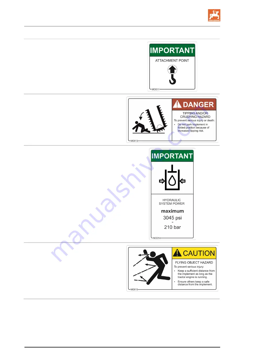


MO011 

Attachment Point 

This symbol indicates lifting points for fastening 
slings when loading the implement. 


MO013 

Tipping and/or Crushing Hazard 

To prevent serious injury or death: 


Do not park implement in folded position 
because of increased risk. 


MO014 

Hydraulic System Power 

The maximum operating pressure of the hydrau-
lic system is 3045 psi [210 bar]. 


MO015 

Flying Object Hazard 

To prevent serious injury: 


Keep a sufficient distance from the imple-
ment as long as the tractor engine is run-
ning. 


Ensure that others keep a safe distance 
from the implement. 


Содержание Catros 3001

Страница 1: ...3501 Catros 4001 Catros 4002 2 Catros 5002 2 Catros 6002 2 Catros 4002 2 Catros 5002 2 Catros 6002 2 Compact Disk Harrow MG4780 BAG0053 14 10 17 Printed in Germany Please read understand and follow this operator s manual before operation Keep it in a safe place for future use en US ...

Страница 2: ... in question would not only harm himself but also make the mistake of blaming the implement for possible failures instead of himself In order to ensure success one should enter the mind of a thing make himself familiar with every part of the implement and get accustomed with how it is handled Only in this way could one be satisfied both with the implement and with him self This is the goal and pur...

Страница 3: ...R GmbH Co KG Postfach 51 D 49202 Hasbergen Germany Phone E mail 49 5405 501 0 amazone amazone de Spare part orders Spare part lists are freely accessible in the spare parts portal www amazone de Please send spare parts orders to your AMAZONE dealer Operator s manual information Document number MG4780 Compilation date 01 17 Copyright AMAZONEN WERKE H DREYER GmbH Co KG 2017 All rights reserved The r...

Страница 4: ... the implement Only after careful reading of this manual will you be able to benefit from the full scope of your newly purchased implement and will be able to operate this implement in a safe manner Please ensure that all implement operators have read this operator s manual before they operate this implement Should you have problems or questions please consult this opera tor s manual or give your ...

Страница 5: ...tion 21 2 15 Safety conscious operation 21 2 16 Safety information for users 22 2 16 1 General safety and accident prevention 22 2 16 2 Hydraulic system 25 2 16 3 Electrical system 26 2 16 4 Cleaning maintenance and repairs 26 3 Loading and unloading 27 4 Product description 28 4 1 Overview of implement assembly 28 4 2 Safety and protection equipment 29 4 3 Power supply cables between tractor and ...

Страница 6: ...7 9 Transportation 68 9 1 Converting from operational to transport position 69 10 Use of the Implement 71 10 1 Converting from transport to operational position 72 10 2 Use in the field 73 10 3 Headland turning 73 11 Faults 74 11 1 Uneven working depths across the working width 74 12 Cleaning maintenance and repairs 75 12 1 Cleaning 75 12 2 Lubrication specifications 76 12 2 1 Lubricants 76 12 2 2...

Страница 7: ...tor s manual are always viewed in the direction of travel 1 3 Diagrams Instructions for action and reactions Tasks to be carried out by the operator are presented as numbered instructions Always follow the order of the instructions The reactions to the instructions are given by an arrow Example 1 Instruction for action 1 Reaction of the implement to instruction for action 1 2 Instruction for actio...

Страница 8: ... state replace damaged warning labels If you still have questions please contact your Amazone dealer Obligations of the operator Before starting work all persons working with on the implement are obligated to comply with the basic workplace safety instructions and accident prevention regulations read and understand the section General safety information of this operator s manual read the section W...

Страница 9: ...owner or field operations manager at the latest on the completion of the purchase contract Guarantee and liability claims for damage to people or goods will be excluded if they can be traced back to one or more of the following causes improper use of the implement improper installation commissioning operation and mainte nance of the implement operation of the implement with defective safety equipm...

Страница 10: ...diate death or serious physical injury WARNING indicates a medium risk which could result in death or serious physical injury if not avoided Failure to follow these instructions may result in death or seri ous physical injury CAUTION indicates a low risk which could result in minor or moderate physical injury and or damage to property if not avoided IMPORTANT indicates a specific obligation or req...

Страница 11: ...arly 2 4 Safety and protective equipment Before each operation of the implement all the safety and protective equipment must be properly attached and fully functional Check all safety and protective equipment regularly Faulty safety equipment Faulty or disassembled safety and or protective equipment can lead to dangerous situations 2 5 Additional safety measures As well as all of the safety inform...

Страница 12: ... company 2 Instructed persons are those who have been instructed in their assigned tasks and in the possible risks in the case of improper behavior have been trained if necessary and have been in formed about the necessary protective equipment and measures 3 People with specialist technical training shall be considered as a specialist Due to their specialist training and their knowledge of the app...

Страница 13: ...lic system from unintentional start up Carefully fix and secure larger subassemblies to lifting gear when carrying out replacement work Regularly check that bolted connections are firmly secured and tight en if necessary When the maintenance work is completed check the function of the safety devices 2 10 Constructive modifications You may not make changes additions or modifications to the implemen...

Страница 14: ...arties there is no guarantee that they have been designed and manufactured in such a way as to meet the requirements placed on them AMAZONEN WERKE accepts no liability for the damage arising from the use of unapproved spare parts wear parts or auxiliary materials 2 11 Cleaning and disposal Handle and dispose of any materials used carefully especially when carrying out work on lubrication systems a...

Страница 15: ...ctions Catros BAG0053 14 10 17 15 2 13 Warning labels and safety markings on the implement 2 13 1 Positioning of warning labels The following diagrams show the arrangement of the warning labels on the implement Fig 1 Fig 2 ...

Страница 16: ...G0053 14 10 17 Warning labels Fig 3 Fig 4 0 Always keep all the warning labels on the implement clean and in a legible state Replace illegible warning labels You can obtain the warning labels from your dealer using the order number e g MO007 ...

Страница 17: ... Field 3 explains the type of hazard as well as how to avoid it Field 4 where the order number is located Warning label explanation In the following pages the individual warning labels will be explained in more detail The column on the left Order number and explanation provides an explanation of the warning pictorial on the right The description of the warning labels always follows the same order ...

Страница 18: ...eep others clear of moving parts MO003 Moving Wing Hazard To prevent serious injury or death Stand clear of wings when being folded or unfolded Keep others clear of wings MO004 Pinching Hazard To prevent serious injury or death Secure implement and wait for all parts to stop moving before reaching into danger area Keep others clear of danger area and mov ing parts MO006 Blade Hazard To prevent ser...

Страница 19: ...achinery MO009 Run Away Hazard To prevent serious injury implement damage and or death Secure implement from accidental rolling before disconnecting from tractor Use parking blocks or chocks to secure implement MO010 Electrocution Hazard To prevent serious injury or death Keep away from power lines when trans porting folding and unfolding implement Electrocution can occur without actual con tact t...

Страница 20: ...prevent serious injury or death Do not park implement in folded position because of increased risk MO014 Hydraulic System Power The maximum operating pressure of the hydrau lic system is 3045 psi 210 bar MO015 Flying Object Hazard To prevent serious injury Keep a sufficient distance from the imple ment as long as the tractor engine is run ning Ensure that others keep a safe distance from the imple...

Страница 21: ...rough non secured working areas failure of important implement functions failure of required methods of maintenance and repair danger to people through mechanical and chemical impacts risk to environment through leakage of hydraulic fluid 2 15 Safety conscious operation In addition to the safety information in this operator s manual the national general workplace safety and accident prevention reg...

Страница 22: ...tions the driving characteristics of the tractor and the connected implement Connecting and disconnecting the implement Only connect and transport the implement with tractors suitable for the task When connecting the implement to the tractor three point hydraulic system the attachment categories of the tractor and the implement must be the same Connect the implement to the required equipment in ac...

Страница 23: ... ensure that you understand all the equipment and set up elements of the implement and their functions There is no time for this when the implement is in operation Do not wear loose fitted clothing Loose clothing increases the risk of being caught by drive shafts and other sharp extruding objects on the implement Only start up the implement when all the safety equipment has been attached and is in...

Страница 24: ...rake delay for the loaded vehicle combination tractor plus connected implement Check the brakes before driving on public roads When turning corners with the implement connected take the gross and balance weight of the implement into account Before transport ensure sufficient side locking of the tractor lower links when the implement is fixed to the three point hydraulic system or lower links of th...

Страница 25: ...take out the ignition key Have the hydraulic hose line checked at least once a year by a specialist for proper functioning Replace the hydraulic hose line if it is damaged or worn Only use AMAZONE original hydraulic hose lines The hydraulic hose lines should not be used for longer than six years including any storage time of maximum two years Even with proper storage and approved use hoses and hos...

Страница 26: ...on to the onboard power supply the user must check whether the installation might cause faults on the vehicle electronics or other components ο Ensure that the retrofitted electrical and electronic components comply with the EMC directive 2004 108 EEC in the appropriate version and carry the CE label 2 16 4 Cleaning maintenance and repairs Only carry out cleaning maintenance and repair work on the...

Страница 27: ... crane CAUTION When loading the implement using a lifting crane use the attachment points for lifting belts Fig 5 CAUTION The minimum tensile strength of each lifting belt must be 2205 lb 1000 kg The implement has 4 attachment points for lifting belts indicated by the sticker order number MO011 ...

Страница 28: ...er understand the implement The implement is composed of the following main components Rigid frame Catros 3001 3501 and 4001 Hydraulically foldable frame Catros 4002 2 5002 2 6002 2 Two row concave disk arrangement Finishing roller 4 1 Overview of implement assembly Fig 6 1 Three point attachment 2 1st disk row 3 2nd disk row 4 Offset disk adjustment 5 Setting spindle for depth adjustment alternat...

Страница 29: ...n equipment Catros 2 1 Stop valve to prevent activating an uninten tional unfolding action from the tractor via the pull cord operated valve ο Stop valve in position A hydraulic un folding locked ο Stop valve in position B hydraulic un folding unlocked through activation of the pull cord operated valve Fig 8 4 3 Power supply cables between tractor and implement Hydraulic hose lines Electric cable ...

Страница 30: ...uare 3 Red reflectors Fig 9 Fig 10 1 2 Warning signs square 2 2 Limiting lights turn indicators Connect the lighting system to the tractor via the 7 pin terminal plug Fig 10 Fig 11 1 2 red retro reflective stickers 2 2 red orange non reflective stickers 3 2 yellow retro reflective stickers 4 1 SMV symbol 5 1 Mounting kit for SMV symbol Fig 11 ...

Страница 31: ...ction of travel to right 15 Along the gradient Uphill 15 Uphill 10 6002 2 6003 2 Downhill 15 The intended use also includes compliance with all the instructions in this operator s manual execution of inspection and maintenance work exclusive use of AMAZONE original spare parts Other uses to those specified above are prohibited and shall be con sidered as improper For any damage resulting from impr...

Страница 32: ...opriate section shall be valid No person may stand in the implement danger area as long as the tractor engine is running with a connected PTO shaft hydraulic system electrical as long as the tractor and implement are not protected against unintentional start up and running The operator may only move the implement or switch or drive the tools from the transport position to the operational position ...

Страница 33: ... 4 3500 13 45 4568 9 68 2950 9 68 2950 9 68 2950 Transport height ft mm 5 58 1700 5 58 1700 5 58 1700 8 2 2500 9 84 3000 11 48 3500 Total length ft mm 8 04 2450 8 04 2450 8 70 2650 8 69 2650 8 69 2650 8 69 2650 Working width ft mm 9 84 3000 11 48 3500 13 12 4000 13 12 4000 16 04 5000 19 69 6000 No of discs 2 x 12 2 x 14 2 x 16 2 x 16 2 x 20 2 x 24 Disk diameter in mm Catros 18 11 460 Catros 20 08 ...

Страница 34: ...705 320 794 360 882 400 1058 480 1235 560 650 mm 1345 610 1543 700 1742 790 1896 860 2337 1060 2690 1220 Winkelprofilwalze lb kg 794 360 904 410 1036 470 1102 500 1323 600 1587 720 U profile roller lb kg 816 370 926 420 1058 480 1146 520 1367 620 1631 740 Double U profile roller lb kg 1146 520 1300 590 1455 660 1676 760 1940 880 2293 1040 Disc roller lb kg 1433 650 1642 745 1852 840 2028 920 2447 ...

Страница 35: ...t description Catros BAG0053 14 10 17 35 Adapter category 4 lb kg 370 168 category 5 396 180 The base weight empty weight is derived from the sum of individual weights of the base implement and its components ...

Страница 36: ...l system Battery voltage 12 V volts Lighting socket 7 pin Hydraulic system Maximum operating pressure 3045 psi 210 bar Tractor pump power At least 3 96 gpm 15 l min at 2175 psi 150 bar Implement hydraulic fluid HLP68 DIN 51524 The implement hydraulic fluid is suitable for the combined hydraulic fluid circuits of all standard tractor brands Control units Depending on equipment see page 38 Three poi...

Страница 37: ...ectly after harvesting seedbed preparation in spring for corn or sugar beet incorporation of cover crops e g yellow mustard incorporation of liquid manure The Catros is attached to the tractor with a three point attachment The two row disk arrangement ensures soil cultivation and proper mixing of the soil The finishing roller serves to reconsolidate the soil and to adjust the depth of the disks Th...

Страница 38: ...activa tion depending on the hydraulic function Latched for a permanent oil circulation Tentative activate until the action is executed Float position free oil flow in the control unit Marking Function Tractor control unit blue foldable machine fold out double acting fold in green working depth Optional increase double acting decrease beige Offset of the disc gangs option reducing Double acting WA...

Страница 39: ...e hydraulic plug into the hydraulic socket until the hy draulic plug is locked in Check the connecting points of the hydraulic hose lines for a good tight fit 1 Adjust the operating lever on the control valve of the tractor to the float position neutral position 2 Clean the hydraulic connectors of the hydraulic hose lines be fore you connect the hydraulic hose lines to the tractor 3 Connect the hy...

Страница 40: ...filling and is mainte nance free The following are adjustable The offsetting of the two disk rows is ad justed via the offset slide Fig 14 2 to working depth and speed Adjustment is made with the AMAZONE eccentric pins The working intensity of the disks over the working depth of the disk harrow can be ad justed The depth is adjusted ο mechanically by means of setting spindles or ο hydraulically vi...

Страница 41: ...must be locked in the transport position They are locked and unlocked via a pull release cord from the tractor The disk rows are locked when the locking pawls Fig 17 1 on the left and right of the disk rows enclose the round steel Fig 17 2 Fig 17 1 locking pawl 2 round steel 3 indicator 4 pull release cord Fig 17 ...

Страница 42: ... the bottom group of holes Provides very good crumbling Cage roller ο SW520 ο SW600 The cage roller can be used where lighter reconsolidation of the soil is required Disposes of a very good self propulsion Wedge ring roller KW580 with adjustable scraper Very well suited for medium soils Wedge ring roller KWM 650 with Matrix profile and adjustable scraper Very well suited for light medium and heavy...

Страница 43: ...load bearing capacity Angle profile roller WW580 The angle profile roller is equipped with an adjustable cutting bar as an option Raising the knife holder with increased organic matter content reduces the risk of blocking Very well suited for medium and heavy soils Unsuitable for stony soils Disc roller DW600 Very well suited for light medium and heavy soils Provides very good crumbling Resistant ...

Страница 44: ...nection point Category 3 2 Lower connection point Category 3 3 Upper connection point Category 2 4 Lower connection point Category 2 Fig 19 Catros 4002 2 5002 2 6002 2 Fig 20 1 Upper connection point Category 3 2 Lower connection point Category 3 3 Upper connection point Category 2 4 Lower connection point Category 2 Fig 20 ...

Страница 45: ... possible to connect the implement to a tractor with a Quick Hitch Fig 21 Mounting 1 Lift Quick Hitch adapter using a lifting crane 2 Attach the Quick Hitch adapter using bolts for the lower imple ment attachment points 3 Attach the upper point of the Quick Hitch adapter using a bolt and secure with a linchpin ...

Страница 46: ...an swing freely to the rear 2 Position of the positioning pin to lock the exact following harrow during road transport 3 Install the road safety bar for road transport 4 Depending on the harrow system adjust the harrow height so that it is free of play Fig 22 Make the same adjustments on all of the setting points Raise and peg the harrow to take it out of operation Attach the transport safety bars...

Страница 47: ...re and function Catros BAG0053 14 10 17 47 Harrow system 12 284 Hi For rollers TW520 380 DUW580 Fig 25 Spring blade system 142 For roller WW580 Fig 26 Spring mounted clearing system 167 For roller UW580 Fig 27 ...

Страница 48: ...ssible to optimize the penetration of the disks into the soil One set of additional weights is equal to 4 times 55 lb 25 kg Catros 3001 3501 and 4001 Install max 2 sets Catros 4002 2 5002 2 6002 2 Install max 3 sets Mounting the additional weights 1 Mount the holder tube Fig 28 1 with four bolts Fig 28 2 on the outside of the wing 2 Install two additional weights Fig 28 3 onto each holder tube Fig...

Страница 49: ...d cover crops during soil cultivation with the Catros disk harrow 1 GreenDrill 2 Folding access ladder 3 Bolt with linchpin to secure the foldable ladder Fig 30 See also the GreenDrill operator s manual Fold the access ladder to transport position before driving and secure it in the transport position using bolt and linchpin Use the step of the ladder as a han dle ...

Страница 50: ...ple for filling the tank Fig 31 1 Rotary knob blue pause time standard 2 hours 2 Rotary knob red lubrication time standard 8 minutes 3 Button for starting the lubrication cycle 4 Sealing cap Fig 32 Set the rotary knob according to the table Do not set the rotary knob to 0 Pause times Rotary knob blue 1 2 3 4 5 6 7 8 9 A B C D E F Hours 1 2 3 4 5 6 7 8 9 10 11 12 13 14 15 Lubrication times Rotary k...

Страница 51: ...51 Lubrication recommendation When applying slurry Initial use Pause time 2 hours Later Pause time 2 4 hours No slurry Lubricate once a day Connection 1 red 2 brown The direction of rotation of the pump must match with the arrow on the hopper Fig 33 ...

Страница 52: ... is suitable for the task The tractor and implement must meet the national road and traf fic regulations The owner or field operations manager and operator shall be responsible for compliance with the statutory road traffic regula tions WARNING Risk of contusions cutting catching drawing in and knocks in the area of hydraulically or electrically operated components Do not block the operator contro...

Страница 53: ...l weight approved axle loads approved drawbar load at the tractor connection point load capacity of the installed tires approved trailer load must be sufficient You can find this data on the identification plate or in the vehicle documentation and in the tractor operator s manual The front axle of the tractor must always be subjected to at least 20 of the base weight empty weight of the tractor Th...

Страница 54: ...r and front im plement mounting or front weight or meas ure a1 ft m Distance from the center of the front axle to the center of the lower link connection See tractor operator s manual or measure a2 ft m Distance between the center of the lower link connection point and the center of gravity of the front implement mount or front weight center of gravity distance See technical data of front implemen...

Страница 55: ...e tractor operator s manual in the table Section 7 1 1 7 6 1 1 4 Calculation of the actual total weight of the combined tractor and implement H L V tat F T G G Enter the numeric value for the calculated actual total weight and the approved total tractor weight specified in the tractor operator s manual in the table Section 7 1 1 7 6 1 1 5 Calculation of the actual rear axle load of the tractor TH ...

Страница 56: ...t stability and insufficient trac tor steering and or brake power It is prohibited to connect the implement to the tractor used as the basis for calculation if one of the actual calculated values is greater than the approved value there is no front weight if required attached to the tractor for the minimum front ballast GV min Ballast your tractor with weights at the front or rear if the tractor a...

Страница 57: ...or engine is running with the PTO shaft hy draulic electric system connected ο with the ignition key in the tractor and the tractor engine can be started unintentionally with the PTO shaft hydraulic electric system connected ο when the tractor and implement have not each been pre vented from unintentionally rolling away by applying the parking brakes and or securing them with wheel chocks ο when m...

Страница 58: ... s three point hydrau lic system only from the intended workstation only if you are outside of the danger area between the tractor and the machine 7 1 Connecting the implement via Quick Hitch The implement must have a Quick Hitch adapter 7 1 1 Connecting the implement 1 Direct people out of the danger area between the tractor and implement before you approach the implement with the tractor 2 First...

Страница 59: ...y 10 in 25 cm forward The resulting free space between the tractor and the im plement provides better access to the supply lines when disconnecting them 2 4 Secure the tractor and implement against unintentional starting and unintentional rolling away 2 5 Disconnect the supply lines 7 2 Connecting the implement the three point attachment frame WARNING Risk of crushing between the rear of the tract...

Страница 60: ...ttachment categories of the tractor and the implement are the same Be absolutely certain to upgrade the category II upper and lower link pins of the implement to category III using reducing sleeves if your tractor has a category III three point linkage Only use the upper and lower link pins provided for connecting the implement Visually check the upper and lower link pins for obvious defects whene...

Страница 61: ... tractor 4 1 Drive the tractor towards the implement leaving approxi mately 10 inches 25 cm between the tractor and imple ment 4 2 Secure the tractor from unintentionally starting and rolling away 4 3 Connect the supply lines to the tractor 4 4 Position the lower link hooks so that they are aligned with the lower linking points on the implement 5 Now reverse the tractor all the way to the implemen...

Страница 62: ...n front of the implement so that you can align the tractor with the implement if necessary 1 Park the implement on a level surface with solid ground 2 Disconnect the implement from the tractor 2 1 Relieve the load from the upper link 2 2 Unlock and disconnect the upper link hooks from the tractor seat 2 3 Relieve the load from the lower link 2 4 Unlock and disconnect the lower link hooks from the ...

Страница 63: ...e the tractor and implement against unintentional start up and rolling before making adjustments to the implement page 57 8 1 Setting the working depth The roller provides height adjustment for accurate depth guidance Check the set working depth using the scale located on the carrying arms of the finishing roller Fig 34 and Fig 35 1 Reduce working depth set indicator toward 2 Increase working dept...

Страница 64: ...ting spindle using ratchet 1 Remove clip pin Fig 37 3 2 Engage the adjustable lever Fig 37 2 in the desired direction 3 Extend shorten the spindle Fig 37 1 using the hand lever 4 Secure using the clip pin Fig 37 3 Fig 38 8 1 2 Hydraulic working depth adjustment optional Activate tractor control unit green The working depth is set hydraulically using the scale Fig 38 1 Reduce working depth set indi...

Страница 65: ...y 3 Release clip pins Fig 39 1 and Fig 40 1 4 Rotate eccentric pins Fig 39 2 and Fig 40 2 to the desired setting and insert 5 Secure the clip pin Fig 40 CAUTION Crushing hazard between eccentric pin and stop of disk row Fig 41 The recommended insertion hole is marked with an arrow Fig 39 3 Catros Preferential insertion hole one place further to right Catros 2 have one possible disk offset setting ...

Страница 66: ...t setting of disk rows Fig 43 Adjust 1st disk row to right and check again Fig 44 The cutting edge of the 2nd disk row is not visible and follows the 1st disk row Adjust 1st disk row to left Fig 44 Fig 45 Fig 46 8 3 Working depth of the outside disks The outside disks on the front right and rear left may be adjusted Use the bearing pin and hub as handle 1 Secure the tractor against unintentional s...

Страница 67: ...entional starting and or rolling away 2 Release the tension bolt Fig 46 1 below the scraper 3 Adjust the scraper in the slotted hole 4 Retighten the tension bolt Fig 48 Wedge ring rollers Do not adjust the distance between stripper and spacer ring to less than 10 mm to avoid excessive wear Tooth packer roller Adjust the distance between the scraper and shaft between 0 5 to 4 mm ...

Страница 68: ...G Risk of crushing cutting catching being drawn in and or being knocked down when making modifications to the implement through unintentional implement movements On foldable implements check that the transport locks are locked correctly Secure the implements against unintentional movements before starting transportation WARNING Risk of contusions cuts dragging catching and or being knocked down by...

Страница 69: ...or climb on the imple ment 9 1 Converting from operational to transport position Catros 3001 and 3501 DANGER Risk of injury with overwidth transport Push in and lock the outer border discs border tines The disk rows must each be locked in the transport position by means of a ratchet on the left and right of the implement 1 Lower the implement 2 Pull the tractor release cord 3 With the implement lo...

Страница 70: ...implement 4 Clean the central tools 5 Clean the lighting 6 Lift the implement so that there is sufficient ground clearance for transport Fig 49 Folded implement in transport position Fig 51 Catros 6002 2 Pay attention to the height of the Catros in transport position and any bridges or other obstacles that may catch on the wings while trans porting Rear harrow optional WARNING Before folding the i...

Страница 71: ...ive in such a way that you always have full control over the tractor with the attached implement In doing so take your personal abilities into account as well as the road traffic visibility and weather conditions the driving characteris tics of the driver and the connected implement WARNING Risk of being crushed cut caught drawn in and or struck if the implement is unintentionally released from it...

Страница 72: ...3501 1 Lower the implement 2 With the implement is lowered reverse on the field 3 Pull the release cord from the tractor and drive forwards Unlock the disk rows Driving forwards with the implement low ered moves the disks to operational posi tion Disk rows unlocked Fig 51 Right implement side pos B Fig 52 Left implement side Catros 4001 The transport position corresponds to the opera tional positi...

Страница 73: ...is ing or positioning the device in headland Fig 55 The device must be adjusted at the lifting wing spindles and the upper link of the tractor so that the frame is parallel to the soil surface longi tudinally and transversely during the work procedure 10 3 Headland turning When turning through a curve at the headland the disc rows must be raised to prevent transverse stresses Only use in headland ...

Страница 74: ...ait for the implement to stop before entering the implement danger area 11 1 Uneven working depths across the working width Catros 2 with hydraulic working depth adjustment Different working depths across the working width Synchronize the hydraulic cylinders For a uniform working depth across the entire implement width it is necessary for the hydraulic cylinders for depth adjustment to be of the s...

Страница 75: ...mineral oils After cleaning grease the implement in particular after cleaning with a high pressure cleaner stream jet or fat soluble agents Observe the statutory requirement for the handling and removal of cleaning agents Cleaning with a high pressure cleaner steam jet Always observe the following points when using a high pressure cleaner steam jet for cleaning ο Do not clean any electrical compon...

Страница 76: ...the implement are indicated with this orange decal Fig 55 Carefully clean the lubrication nipple and grease gun before lubrication so that no dirt is pressed into the bearings Press the dirty grease out of the bearings completely and replace it with new grease Fig 57 12 2 1 Lubricants For lubrication work use a lithium saponified multipurpose grease with EP additives Company Lubricant ARAL Aralub ...

Страница 77: ...ion point overview Fig 56 Lubrication point Interval h Quantity Catros 2 1 Center section joint bearing right and left 50 4 2 Working depth above setting spindle or 50 4 Catros pro 2 Working depth above hydraulic cylinder 50 8 Catros 2 3 Hydraulic cylinder folding 50 4 Fig 58 ...

Страница 78: ...bolts of clamping brackets Specified tightening torque 155 ft lb 210 Nm 81 Daily Component Service work See page Specialist workshop Electric lighting Changing defective bulbs 86 Weekly every 50 working hours Component Service work See page Specialist workshop Hydraulic hose lines Check 85 X Every 4 months 200 working hours Component Service work See page Specialist workshop Roller Retighten bolts...

Страница 79: ...nk pin Replace 81 Whole implement Alignment 83 12 4 Replacing the discs Workshop work Minimum disc diameter 360 mm The discs are replaced with the machine folded out the discs raised the machine secured against unintentional lowering 1 Release the four screws securing the disc 2 Remove the disc 3 Secure the new disc with four screws Fig 59 Fig 60 Fig 61 CAUTION When removing spring suspended eleme...

Страница 80: ...rt the disk units Each disk unit has two slide bearings 1 Release the locking bolt Fig 60 2 of the sliding shaft Fig 60 3 2 Drive the sliding shaft out of the bearing 3 Remove the circlips from the slide bearing 4 Replace the slide bearing 5 Fit the circlips 6 Reinstall the sliding shaft and secure with a locking bolt Fig 62 12 6 Finishing roller workshop work To replace the roller Fig 61 1 lower ...

Страница 81: ...bracket and its bolts must be installed according to Fig 62 12 8 Disk attachment Check the bolts for tightness Required tightening torque 155 ft lb 210 Nm Fig 65 12 9 Top and lower linkage pins WARNING Risk of crushing catching and being knocked down when the implement unexpectedly detaches from tractor Check the upper and lower linkage pins for visible damage each time you connect the implement R...

Страница 82: ...y attached to the hydraulic cylinder Required tightening torque for lock nut on hydraulic cylinder for folda ble wings 220 ft lb 300 Nm Check the pin connections on the hydraulic cylinders Fig 64 1 every six months Fig 66 Fig 65 Specified screw in depth Fig 67 Fig 66 Tightening torque 220 ft lb 300 Nm Use bolt locking compound KA071 Fig 68 ...

Страница 83: ...ss state Aligning the boom parallel to the ground Adjust the length of the hydraulic cylinder such that both lateral frames are parallel to the ground when in working position on a level surface Fig 69 Aligning the rollers with each other Adjust the length of the completely extended hydraulic cylinder such that both rollers are at the same height when the implement is raised Before doing so synchr...

Страница 84: ...e and the trailer Ensure that the hydraulic hose lines are connected correctly Regularly check all the hydraulic hose lines and connections for damage and irregularities Have the hydraulic hose line checked at least once a year by a specialist for proper functioning Replace the hydraulic hose line if it is damaged or worn Only use AMAZONE original hydraulic hose lines The hydraulic hose lines shou...

Страница 85: ... worn or damaged hydraulic hose lines immediately 12 12 3 Inspection criteria for hydraulic hose lines For your own safety comply with the following inspection criteria Replace hydraulic hose lines upon discovering any of the follow ing during inspection damage to the outer layer up to the ply e g rubbing points cuts and cracks brittleness of outer layer crack formation of the hose material deform...

Страница 86: ...ter mechanical influences on the hydraulic hose lines are avoided use appropriate arrangements and fixing to prevent any rubbing of the hoses on components or on each other If necessary secure hydraulic hose lines using protective co vers Cover sharp edged components ο the approved bending radii may not be exceeded When connecting a hydraulic hose line to moving parts the hose length must be appro...

Страница 87: ...Cleaning maintenance and repairs Catros BAG0053 14 10 17 87 12 14 Hydraulics diagram Folding Fig 72 Working depth Fig 73 ...

Страница 88: ...Cleaning maintenance and repairs 88 Catros BAG0053 14 10 17 Offset of the disc gangs Fig 74 ...

Страница 89: ...485 M 18x1 5 240 325 339 460 406 550 M 20 30 302 410 428 580 509 690 M 20x1 5 339 460 472 640 568 770 M 22 32 406 550 575 780 686 930 M 22x1 5 450 610 634 860 774 1050 M 24 36 524 710 738 1000 885 1200 M 24x2 575 780 811 1100 959 1300 M 27 41 774 1050 1106 1500 1328 1800 M 27x2 848 1150 1180 1600 1438 1950 M 30 46 1070 1450 1475 2000 1770 2400 M 30x2 1180 1600 1660 2250 1991 2700 M M4 M5 M6 M8 M10...

Страница 90: ......

Отзывы: