background image

15

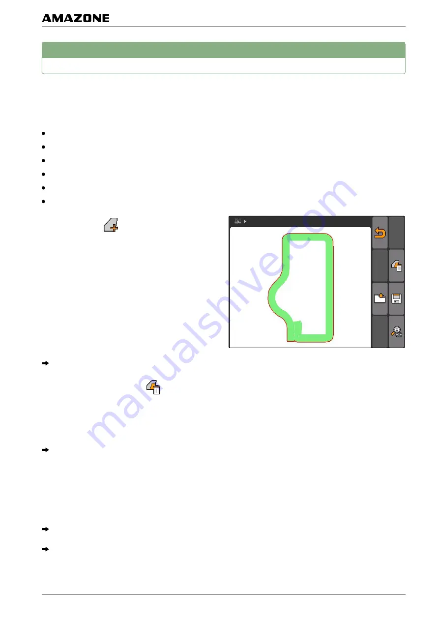
Deleting recorded field data

All recorded field data can be deleted. The field data can
be previously saved to the USB flash drive.

The field data includes the following data:

Field boundary

Worked area

Track lines

Obstacles

Application maps

Headlands

1.

"GPS switch"

 >

.

The field data menu will be opened.

2. In the field data menu, select

.

3.

If the field data should be deleted without saving
the field data to the USB flash drive,

select 

"No"

.

The field data will be deleted from the current job.

4.

If the recorded field data should be saved to the
USB flash drive before deleting the field data,

select 

"Yes"

.

5. Enter the name for the field data and confirm.

The field data will be saved to the USB flash drive.

The field data will be deleted.

009609

K | Using the GPS switch| Deleting recorded field data

MG5560-EN-II

 | B.1 | 2016.07

111

Содержание AMATRON 3

Страница 1: ...Operating instructions MG5560 EN II B 1 22 07 2016 Control terminal AMATRON 3 Original operating instructions ...

Страница 2: ......

Страница 3: ...gs 22 1 1 Entering the basic settings 23 1 2 Configuring ISOBUS 27 1 3 Setting up the interfaces 28 1 4 Configuring the toggle button 32 1 5 Defining the start mode 32 1 6 Configuring parallel operation 33 2 Defining the AUX N assignment 33 2 1 Defining the AUX N assignment using the functions list 34 2 2 Defining the AUX N assignment using the input list 35 2 3 Deleting the selected AUX N assignm...

Страница 4: ...ing the on off point delays 88 3 10 Determining the correction times for on off point delays 89 3 11 Checking the switch on and off times 90 4 Zooming the map 91 5 Panning the map 92 6 Turning around the orientation of the tractor symbol 92 7 Marking obstacles 93 8 Deleting an obstacle marking 94 9 Creating the field boundary 94 10 Deleting the field boundary 95 11 Creating virtual headlands 96 11...

Страница 5: ...L Using the AUX N menu 123 M Eliminating faults 124 N Maintenance 126 1 Performing the software update 126 Indexes 1 GLOSSARY 128 2 INDEX 130 TABLE OF CONTENTS MG5560 EN II B 1 2016 07 3 ...

Страница 6: ...ep the operating manual available 3 Hand over the operating manual to the subsequent user 2 Other applicable documents Operating manual for the GPS receiver Operating manual for the implement software 3 Validity These operating instructions are valid for software ver sion 01 08 00 For information on the software version Setup Diag nosis Software versions 020869 020879 020877 020867 A About this op...

Страница 7: ...ce of the instructions The re action to the respective action is marked with an arrow 1 Action 1 Implement reaction to Action 1 2 Action 2 Instructions with alternative action Alternative instructions are introduced with the word or Example 1 Action or Alternative action 2 Action Instructions with only one action Instructions with only one action are not numbered but rather shown with a tilted arr...

Страница 8: ...Entry 1 Entry 2 Entry 3 4 4 Item numbers Item numbers in the text or in the legend refer to item numbers in figures located beside or above the text The item numbers in the figures can be connected with item lines 1 Item 1 2 Item 2 3 Item 3 4 5 Orientation paths Orientation paths located at the beginning of text sec tions with instructions for action help with rapid orienta 021155 007273 007274 02...

Страница 9: ...are updated regular ly Your suggestions for improvement help us to create ever more user friendly operating manuals Please send us your suggestions by post fax or email AMAZONEN WERKE H DREYER GmbH Co KG P O Box 51 D 49202 Hasbergen Fax 49 0 5405 501 234 Email td amazone de 000220 A About this operating manual Your opinion is important MG5560 EN II B 1 2016 07 7 ...

Страница 10: ...ISO BUS wiring The tractor basic equipment console with distribu tor must be mounted in the cab vibration free and with a conductive connection to the right of the driv er within his view and reach The distance from the radio unit or antenna must be at least 1 m 3 The paint must be removed from the installation points in order to prevent electrostatic charge 018762 B Assembly instructions MG5560 E...

Страница 11: ...ode For implements that are connected to an ISOBUS tractor using the ISOBUS light cabling Disable the ISOBUS function of the tractor terminal 018763 B Assembly instructions Mounting for ISOBUS mode MG5560 EN II B 1 2016 07 9 ...

Страница 12: ...2 Mounting for AMABUS mode 018764 B Assembly instructions Mounting for AMABUS mode MG5560 EN II B 1 2016 07 10 ...

Страница 13: ...3 Mounting for parallel operation 018765 B Assembly instructions Mounting for parallel operation MG5560 EN II B 1 2016 07 11 ...

Страница 14: ...y 3 Directional pad Change the selection on the display change numerical values confirm selections 4 ACK Acknowledge messages from the Universal Terminal In AMABUS mode Scroll through the imple ment controls 5 Escape Back cancel 6 On Off button Switching the AMATRON 3 on and off 020885 020886 C AMATRON 3 overview MG5560 EN II B 1 2016 07 12 ...

Страница 15: ...ey for the work menu of the implement controls Rating plate and CE mark The following information is listed on the rating plate 1 Implement ID no 2 Type 020887 021015 021014 C AMATRON 3 overview Rear side MG5560 EN II B 1 2016 07 13 ...

Страница 16: ...To switch to the main menu press and hold NOTE The menus for the toggle button can be selected in the setup menu see page 32 In the factory settings the GPS switch is enabled by default If other implements such as a sprayer AmaPi lot or new ISOBUS compatible implements are on the bus they are automatically enabled 021082 006867 D Basic operation MG5560 EN II B 1 2016 07 14 ...

Страница 17: ...ocedures the corresponding F key must be pressed To select the top right button To select the top left button 3 Using the directional pad and Move the selection up or down and Move the selection to the left or right Accept the number 4 Entering text When text must be entered a menu is opened with a character area and additional buttons 006868 007433 013428 D Basic operation Using the F keys MG5560...

Страница 18: ...area 2 Add the selected character to the input field with 3 Confirm the entry with or Cancel the entry with 5 Entering numerical values When numerical values must be entered a menu is opened with a number area and additional buttons Number menu overview and Move the cursors left and right Reverses the sign Increases the marked number by 1 Reduces the marked number by 1 Clears the input field 01347...

Страница 19: ... field 3 Confirm the entry with or Cancel the entry with 6 Using the shift key The shift key is needed for the work menu of the imple ment controls When the shift key is active it is shown on the display Press on the rear side of the AMATRON 3 Other function field will be shown which changes the assignment of the function keys 020948 D Basic operation Using the shift key MG5560 EN II B 1 2016 07 1...

Страница 20: ...d implement BUS modes AMABUS ISOBUS NOTE After 10 seconds the AMATRON 3 automatically starts in the previously selected BUS mode If the AM ATRON 3 should start directly in the previously selec ted BUS mode the corresponding mode must be acti vated in the setup see page 32 1 Select the mode with or 2 Confirm with 006865 009911 E After switching on MG5560 EN II B 1 2016 07 18 ...

Страница 21: ...ecog nises external input devices in ISOBUS mode A list with the device functions will be opened The dis played device functions depend on which device is rec ognised first 1 Scroll through the assignment list with and 2 If the AUX N assignments should be changed see page 20 or If the AUX N assignments are correct confirm the AUX N assignments 009912 E After switching on Checking the AUX N assignm...

Страница 22: ...opened 2 Select a desired input button with The input button is assigned to the selected function 3 Assign other functions or Confirm the assignment with NOTE The button assignment can be changed at any time in the setup see page 33 009913 E After switching on Changing the AUX N assignments MG5560 EN II B 1 2016 07 20 ...

Страница 23: ...e symbol varies depending on the connected implement Opens the implement management Configuring the implement see page 43 Opens the AUX N assignment overview Using the AUX N assignment overview see page 123 Opens the tractor management Tractor configura tion see page 48 Opens the job management Managing jobs see page 53 Opens the setup menu Setup menu configuration see page 22 009637 F Main menu o...

Страница 24: ...g the setup G Select Main menu Setup The setup menu will be opened 1 Entering the settings Select Setup Settings The Settings menu will be opened 006870 006876 G Configuring the setup MG5560 EN II B 1 2016 07 22 ...

Страница 25: ...hicle ignition see page 24 Setting the volume of the signal tones and alarm tones see page 24 Setting the display brightness see page 25 Setting the date and time see page 26 Setting the region and language see page 26 1 1 1 Enabling or disabling job management Job management can be used to process jobs in ISO XML format Job management can be enabled or disa bled Job management is disabled per def...

Страница 26: ...MATRON 3 is in ISOBUS mode see page 18 1 Select Setup Settings Basic settings Possible settings When the vehicle ignition is switched on or off the AMATRON 3 is switched on or off The AMATRON 3 must be switched on and off manually 2 Enable or disable ignition switching 1 1 3 Adjusting the volume In this menu the volume of the signal tones can be ad justed 013355 013491 G Configuring the setup Ente...

Страница 27: ... settings Brightness Possible settings Percent value for the display brightness during the day Percent value for the display brightness at night Sets the display brightness to the value entered under Brightness for operation at night Percent value for the brightness of the button illu mination on the AMATRON 3 006886 G Configuring the setup Entering the settings MG5560 EN II B 1 2016 07 25 ...

Страница 28: ...r the current time Value between 13 and 12 for the corresponding time zone 24 hour format or 12 hour format Various date formats DD for the day MM for the month YYYY for the year 1 1 6 Setting the region and language Select Setup Settings Basic settings Re gion and language 006892 006893 G Configuring the setup Entering the settings MG5560 EN II B 1 2016 07 26 ...

Страница 29: ...the only connected terminal the implement automat ically adopts the ISOBUS UT number of the AMATRON 3 2 Under ISOBUS UT number enter the identification number for the Universal Terminal of the AMATRON 3 For job documentation the AMATRON 3 has a clear identification number the Task Controller ID If the job documentation should be saved on the AMATRON 3 the Task Controller ID must match with the Tas...

Страница 30: ...erface the TC ID ASD GPS maps defines where the incoming data should be sent To be able to use the ASD interface and GPS maps the TC ID ASD GPS maps must match with the Task Controller ID 5 Under TC ID ASD GPS maps enter the identifica tion number for the ASD interface and GPS maps 1 3 Setting up the interfaces Select Setup Settings Interfaces Possible settings GPS configuration see page 29 Transf...

Страница 31: ...PS GPS menu overview Call up the GPS information e g the latitude and longitude Reset the GPS receiver if it is not working proper ly Setting up the A100 A101 receiver 1 Select GPS driver A100 101 2 Under Satellite 1 and Satellite 2 select Auto With the Auto setting the GPS receiver automati cally searches for the correct satellites 006902 017823 G Configuring the setup Entering the settings MG556...

Страница 32: ...on services EGNOS WAAS and MSAS For more information on this topic please consult the operating manual for the satellite receiver Setting up other GPS receivers 1 Select GPS driver Other 2 Under Baud rate enter the baud rate for the GPS receiver NOTE More information on the baud rate can be found in the GPS receiver operating manual The connected receiver must send the following messages to the te...

Страница 33: ...a transfer rate must be selected for the connected imple ment The correct baud rate is written in the implement operating manual Select Setup Settings Interfaces AFD baud rate Possible settings 57600 baud 19200 baud 1 3 3 Adjusting the light bar The light bar 1 shows the deviation of the tractor from the guide track and thereby enables precise following of the guide tracks 014001 018888 G Configur...

Страница 34: ... switch among the selected menus and applications 1 Select Setup Settings Toggle button 2 Select the menus that should be reached using the toggle button 1 5 Defining the start mode The AMATRON 3 can be started in 3 different modes Select Setup Settings Start mode 006883 006884 G Configuring the setup Entering the settings MG5560 EN II B 1 2016 07 32 ...

Страница 35: ... one AMATRON 3 can be used to display the implement controls and the other AMATRON 3 for the GPS functions Select Setup Settings Parallel operation Possible settings The AMATRON 3 can be used to access the im plement controls and the GPS functions are available The AMATRON 3 can only be used to access the implement controls The Task Controller is signed off of the BUS Only the GPS functions are av...

Страница 36: ...f available functions will be displayed Possible settings Define the AUX N assignment using the functions list see page 34 Define the AUX N assignment using the input list see page 35 2 1 Defining the AUX N assignment using the functions list For the AUX N assignment using the functions list all of the available functions are listed on the left side The buttons of an external input device can be a...

Страница 37: ... list For the AUX N assignment using the input list all of the available buttons are listed on the left side These but tons can be assigned to functions 1 If the buttons are not listed on the left side Select 2 Select a button from the list The list of available functions will be opened 007528 G Configuring the setup Defining the AUX N assignment MG5560 EN II B 1 2016 07 35 ...

Страница 38: ...o the selected function 2 3 Deleting the selected AUX N assignment 1 Select the desired assignment from the list 2 Select 3 Confirm with Yes The assignment will be deleted 013505 G Configuring the setup Defining the AUX N assignment MG5560 EN II B 1 2016 07 36 ...

Страница 39: ...idth section control GPS track for track guidance GPS maps for variable rate control with application maps in shape format NOTE The 3 applications are activated for a period of use of 50 hours To be able to use the applications without restrictions the license key must be purchased from AMAZONE 007529 006878 G Configuring the setup Using the licence management MG5560 EN II B 1 2016 07 37 ...

Страница 40: ...up Settings License manage ment 2 Select the desired application 3 Press 4 Enter the license key and confirm The application is activated NOTE If the license keys were accidentally deleted press to restore them 4 Using the diagnosis Select Setup Settings Diagnosis 006879 G Configuring the setup Using the diagnosis MG5560 EN II B 1 2016 07 38 ...

Страница 41: ... management is used to manage the data on the in serted USB flash drive Select Setup Settings Diagnosis USB management A list with the data on the USB flash drive will be opened Formatting the USB flash drive 1 If all of the data on the USB flash drive should be deleted Select 2 Confirm with Yes The USB flash drive will be formatted 006907 007533 G Configuring the setup Using the diagnosis MG5560 ...

Страница 42: ...e USB flash drive 4 2 Using the pool management Pool refers to a file that describes the representation of the implement software on the terminal After connecting an implement for the first time or after an update the pool of the implement will be automatically loaded and saved on the terminal A pool can be reloaded if it was previously deleted in the pool management and the ter minal as well as t...

Страница 43: ...agnosis CAN di agnosis 2 Under CAN trace activation set whether the CAN trace should be started manually or after the AMA TRON 3 is restarted 3 Under Runtime set the recording time in minutes 4 If Manual was set under CAN trace activation start the CAN trace with or If After terminal restart was set under CAN trace activation restart the AMATRON 3 The CAN trace has been started 5 To stop the CAN t...

Страница 44: ...n be reset 1 Select Setup Setting Diagnosis Reset 2 To reset the GPS switch settings select Reset GPS switch track 3 To reset the AMATRON 3 settings and delete the data select Factory settings 4 Confirm the reset 006910 G Configuring the setup Using the diagnosis MG5560 EN II B 1 2016 07 42 ...

Страница 45: ... the termi nal Using the entered implement data the AMATRON 3 can control the connected implement The following implement data must be entered Implement name Implement type Geometry data Part width section data ISOBUS implements sign in automatically and do not re quire configuration Select Main menu Implements 006871 H Configuring implements MG5560 EN II B 1 2016 07 43 ...

Страница 46: ...for the selected imple ment see page 44 1 Editing the implement data NOTE The implement data for ISOBUS implements must be edited though the implement controls in the UT setup 1 Select Main menu Implement 2 Add a new implement or Edit an existing implement The Implement data menu will be opened 006926 H Configuring implements Editing the implement data MG5560 EN II B 1 2016 07 44 ...

Страница 47: ...ions un der Standard part width section 7 If a width should be assigned to a specific part width section enter a value for the respective part width section under Part width section no NOTE The numbering of the part width sections is carried out from left to right in the direction of travel 1 1 Editing the implement geometry data For the GPS switch to function properly the implement geometry data ...

Страница 48: ...settings the value X2 can be entered see page 80 If the geometry values for a spreader are changed the headland distance must be changed to the same value in the GPS switch settings see page 84 2 Selecting the implement If one of the following implements is connected this con nected implement must be selected to be able to use GPS switch AMABUS implement Implements that cannot communicate with the...

Страница 49: ...Selectable implements have a check box Mark the desired implement H Configuring implements Selecting the implement MG5560 EN II B 1 2016 07 47 ...

Страница 50: ...cally transmit their data to the AMATRON 3 The ISOBUS tractor must be configured accordingly More information on this topic can be found in the ISOBUS tractor operating manual NOTE A tractor must be configured in the following ca ses The AMATRON 3 is operated in AMABUS mode Data transmission of the ISOBUS tractor is disa bled The data sent by the ISOBUS tractor should not be used Select Main menu ...

Страница 51: ...lected tractor Opens the tractor data for the selected tractor for editing see page 49 1 Editing the tractor data 1 Add a new tractor in the Tractors menu or Edit a selected tractor The Tractor data menu will be opened 2 Enter a name for the tractor under Name 007576 I Configuring tractors Editing the tractor data MG5560 EN II B 1 2016 07 49 ...

Страница 52: ...ight of the centre of the axle enter a positive value for the distance between the GPS receiver and the centre of the axle under A or If the receiver is installed to the left of the centre of the axle enter a negative value for the distance between the GPS receiver and the centre of the axle under A 3 If the receiver is installed in front of the centre of the axle enter a positive value for the di...

Страница 53: ... sensors The tractor sensor must only be configured if the tractor does not have any speed sensors and therefore does not send speed data In the case the speed data can be transmitted to the AMATRON 3 by external sensors e g wheel sensors or GPS sensors REQUIREMENTS The AMATRON 3 is started in ISOBUS mode see page 18 1 Tractor data Sensors The Sensors menu will be opened 007575 I Configuring tract...

Страница 54: ...ed source enter the number of pulses sent by the wheel sensor or radar sensor over a distance of 100 m under Pul ses per 100 m or If the number of pulses per 100 m is not known select Count pulses over 100 m and follow the in structions on the screen 2 Selecting the tractor To use the GPS switch a tractor must be selected REQUIREMENTS Tractor data edited see page 44 Mark the desired tractor The tr...

Страница 55: ...sed Map type 2 This type of map is not displayed on the GPS switch map The stored setpoints are transmit ted to the implement and processed When a job has been started on the AMATRON 3 the field boundaries and the application map are displayed on the GPS switch map and the job data is recorded The recording of job data depends on the created ISO XML job and the connected implement Among others the...

Страница 56: ...job see page 70 and see page 70 Copies the selected job see page 69 Exports the jobs see page 71 Opens the search function see page 69 1 Importing jobs REQUIREMENTS The jobs have been created in ISO XML format The TASKDATA XML file is on the USB flash drive in the Taskdata folder USB flash drive is inserted Job management is enabled see page 23 013998 J Using the job management Importing jobs MG55...

Страница 57: ...FMIS cannot be edited The master data includes the following information Setpoints for application spread rates Field data Customer data Worker data Product data Select Jobs The Master data menu will be opened Possible settings Manage the Setpoints see page 56 Manage the Fields see page 57 Manage the Customers see page 58 Manage the Workers see page 59 Manage the Products see page 60 007606 J Usin...

Страница 58: ...e spread rate for a spreader or seed drill can be defined Select Jobs Setpoints Setpoint menu overview Opens the master data menu Adds a setpoint Deletes the selected setpoint 2 1 1 Editing the setpoints Setpoints can consist of several products to document which product was used for the job To group setpoints from different products the products must be created see page 60 007602 009944 J Using t...

Страница 59: ... set points 4 In the third column select the products NOTE In the product selection menu products can also be created and edited see page 61 5 Confirm entries The total application spread rate and the units are transmitted to the implement In this example Prod uct 1 500 l ha 2 2 Managing fields Fields can be created to document which fields were worked in the respective jobs 007604 J Using the job...

Страница 60: ... field from the list or Add a new field The Field data menu will be opened 2 Enter data and confirm 2 3 Managing the customers Customer data can be added to jobs This enables the documentation of the customers for whom the respective jobs were processed Select Jobs Customers 007613 007603 J Using the job management Managing master data MG5560 EN II B 1 2016 07 58 ...

Страница 61: ...iting the customer data 1 Select a customer from the list or Add a new customer The Customer data menu will be opened 2 Enter the customer data 3 Confirm entries 2 4 Managing workers Worker data can be added to jobs This enables the doc umentation of the working time for each worker Select Jobs Worker 009332 007605 J Using the job management Managing master data MG5560 EN II B 1 2016 07 59 ...

Страница 62: ...orker from the list or Add a new worker The Worker data menu will be opened 2 Enter the worker data 3 Confirm entries 2 5 Managing products Products can be added to the setpoints This enables the documentation of quantities used for each product Select Jobs Products 009335 007607 J Using the job management Managing master data MG5560 EN II B 1 2016 07 60 ...

Страница 63: ...o a product group if data for the product groups was created in a Farm Management Information System This data is auto matically loaded from the USB flash drive 3 Creating a new job With the AMATRON 3 jobs can be created in ISO XML format and edited The created jobs can be exported and further processed with a Farm Management Information System FMIS The following additional data can be added to th...

Страница 64: ...an also be created 5 Confirm entries 3 1 Adding setpoints to a job Controllable implement elements can be assigned with setpoints For example the application rates for a spray er and the spread rates for a spreader or seed drill can be defined The setpoints for the application spread rates can come from the following sources Setpoints created on the AMATRON 3 From an imported application map in sh...

Страница 65: ...rom an applica tion map in shape format Application map in shape format is imported see page 114 If the setpoint should be transmitted with the ASD interface ASD interface is configured see page 31 1 Jobs Select the started job 2 Select Setpoints The Setpoints menu will be opened The controlla ble implement elements will be shown 018624 J Using the job management Creating a new job MG5560 EN II B ...

Страница 66: ...reating a setpoint In this case see page 56 4 Select the desired setpoint from the list The selected setpoint is assigned to the controllable implement element 3 2 Adding a worker to a job Workers can be assigned to a job to record the working time for this worker REQUIREMENTS Worker is created in the master data see page 56 Job is started see page 70 012164 J Using the job management Creating a n...

Страница 67: ...ed workers will be shown Working time recording started Working time recording stopped Opens the selected job Adds a new worker or Start or stop the working time recording for the selected worker 3 To add a worker Select J Using the job management Creating a new job MG5560 EN II B 1 2016 07 65 ...

Страница 68: ...recording for a worker Select 3 3 Adding implements and tractors to a job Implements and tractors can be assigned to a job to re cord the working time for these implements and tractor REQUIREMENTS Implement is configured see page 43 Tractor is configured see page 48 Job is started see page 70 012165 J Using the job management Creating a new job MG5560 EN II B 1 2016 07 66 ...

Страница 69: ...me recording stopped Opens the selected job Opens the menu with the selectable implements and tractors or Start or stop the working time recording for the selected implement or the selected tractor 3 To add an implement or a tractor Select The menu with the selectable implements and trac tors will be shown J Using the job management Creating a new job MG5560 EN II B 1 2016 07 67 ...

Страница 70: ... tractor Select 3 4 Checking the map type If a job with an application map in ISO XML format was imported from the Farm Management Information Sys tem to the AMATRON 3 the map type is shown here Map type 1 The application map is displayed in GPS switch and the setpoints are processed Map type 2 The application map is not displayed in GPS switch but the setpoints are processed 018747 J Using the jo...

Страница 71: ...rm the entry The found jobs are displayed 5 Copying jobs To process jobs with the same data several times the jobs can be copied 1 Jobs Select a job 2 Select 3 Confirm the copying 006930 006931 J Using the job management Searching for jobs MG5560 EN II B 1 2016 07 69 ...

Страница 72: ...shown on the map in GPS switch REQUIREMENTS Job is imported or created Importing jobs see page 54 Creating jobs see page 61 1 Jobs Select a job 2 Select The selected job will be started 7 Stopping a job When a job is stopped the job data is no longer recor ded 006933 006934 J Using the job management Starting a job MG5560 EN II B 1 2016 07 70 ...

Страница 73: ...to the USB flash drive The ex ported jobs can then be further processed with a Farm Management Information System FMIS REQUIREMENTS USB flash drive is inserted Select Jobs All of the jobs will be exported and saved to the USB flash drive 006932 J Using the job management Exporting jobs MG5560 EN II B 1 2016 07 71 ...

Страница 74: ...Using the GPS switch K 1 GPS switch overview 1 1 GPS switch interface overview 1 1 1 Symbols on the map 013347 026186 013353 014003 K Using the GPS switch MG5560 EN II B 1 2016 07 72 ...

Страница 75: ...ed 8 Worked area and remaining area 9 Obstacle 10 Virtual headlands in grey 11 Track line with track line number 12 Mode for the part width section control 1 1 2 Display outside of the map 1 Track line deviation in centimetres arrow symbols for the direction and amplitude of the track line deviation 2 Buttons for the GPS switch menu 3 Implement information 014004 K Using the GPS switch GPS switch ...

Страница 76: ...or delete the track lines or Create field boundary or delete field boun dary or Rotates the vehicle symbol or Switch between zoom and map panning Page 2 Creates the virtual headland and enables it Enables the working of the inside of the field and blocks the virtual headland Deletes the virtual headland Creates an obstacle Deletes the obstacle Opens the GPS switch calibration Opens the GPS switch ...

Страница 77: ...ctions of the connected implement on and off To do so the AMATRON 3 uses the GPS signal from the connected GPS receiver NOTE The connected receiver must send the following messages to the terminal GGA GSA VTG For automatic part width section control the follow ing settings are available Degree of overlap of 0 50 or 100 Overlap tolerances up to 25 cm Overlap tolerances at the field boundary up to 2...

Страница 78: ... coun tersteer accordingly NOTE This application is activated for a period of use of 50 hours To be able to use the application without re strictions a license key must be purchased from AM AZONE 1 2 3 Variable rate control with GPS maps GPS maps enables importing and use of application maps in shape format Application maps can be used to control an element of a connected implement For exam ple th...

Страница 79: ...with job manage ment the following requirements must be met GPS is configured see page 29 For ISOBUS implements and AMABUS imple ments Implement is connected For ISOBUS implements ISOBUS is properly configured see page 27 For AMABUS implements and implements that cannot communicate with the terminal Implement is selected see page 46 The tractor is selected see page 52 Job management is enabled see...

Страница 80: ...oundary and application map created in the job TROUBLESHOOTING Are the contents not shown on the GPS switch map The requirements for starting GPS switch were not met Error symbols are flashing on the GPS switch map 1 Check the requirements for starting GPS switch 2 Restart GPS switch K Using the GPS switch Starting the GPS switch MG5560 EN II B 1 2016 07 78 ...

Страница 81: ...US implements ISOBUS is configured see page 27 For AMABUS implements and implements that cannot communicate with the terminal Implement is selected see page 46 The tractor is selected see page 52 Job management is disabled see page 23 Select Main menu GPS switch GPS switch will be started The following contents are shown on the GPS switch map A tractor symbol An implement symbol 013352 K Using the...

Страница 82: ... GPS switch 2 Restart GPS switch 3 Entering the basic settings for GPS switch Select GPS switch The GPS switch settings will be opened 3 1 Defining the implement modelling The specification of the implement modelling is required to simulate the different following characteristics of the implements 009343 009344 K Using the GPS switch Entering the basic settings for GPS switch MG5560 EN II B 1 2016...

Страница 83: ... implements in the implement geometry da ta see page 45 3 2 Select the source for the driving direction detection The driving direction detection ensures that the tractor symbol does not turn around when the tractor drives in reverse Different sources are possible for the driving di rection detection If the sources do not provide the cor rect driving direction detection the driving direction de te...

Страница 84: ...ection function is not available 3 3 Enabling the acoustic field boundary warning When the vehicle approaches the field boundary the AMATRON 3 can issue a warning tone Select GPS switch Acoustic field boun dary warning 3 4 Defining the map display The map in GPS switch can be displayed in two or three dimensions 1 Select GPS switch Map display 2 Select the desired map display 009338 009333 K Using...

Страница 85: ...switch settings for spreaders 3 6 1 Automatically creating a safety zone This function defines whether a safety zone is automati cally created inside a field boundary REQUIREMENTS For AMABUS spreaders Spreader is connected The AMATRON 3 is started in AMABUS mode see page 18 Spreader is selected in the implement menu see page 46 For ISOBUS spreaders Spreader is connected The AMATRON 3 is started in...

Страница 86: ...nd distance The headland distance 3 is the distance between the headland boundary 4 and the application point of the spreader 2 The spreading can only be started once the application point of the spreader has reached the de fined headland distance When the headland distance is correctly set it prevents the spread fan 1 from reach ing into the headlands 2 3 4 1 013343 K Using the GPS switch Enterin...

Страница 87: ...ering the GPS switch settings for sprayers 3 7 1 Setting the automatic boom lowering The automatic boom lowering automatically lowers the boom when the sprayer moves onto an unworked area NOTE The value to be entered refers to the duration of the lowering procedure The correct timing of the automatic boom lower ing function depends on the following factors Forward speed Tractor equipment Implement...

Страница 88: ... drills 3 8 1 Configuring the driver assistance system The driver assistance system supports the driver in working the field seamlessly Switching delays of the seed drill and uneven forward speeds can cause overlap or underlap in the seed rows The driver assistance sys tem notifies the driver with a signal tone and a symbol that the vehicle is approaching the switch point and that the forward spee...

Страница 89: ...mode see page 18 Seed drill is selected in the implement menu see page 46 For ISOBUS seed drills Seed drill is connected The AMATRON 3 is started in ISOBUS mode see page 18 1 Select GPS switch Driver assistance sys tem 2 Enter the desired distance and confirm or If the driver assistance system should be disabled enter 0 and confirm K Using the GPS switch Entering the basic settings for GPS switch ...

Страница 90: ...set such that the appli cation spreading starts precisely and therefore avoids underlaps The Off point delay must be set such that the appli cation spreading stops precisely and therefore avoids overlaps Boundaries for starting and stopping the applica tion spreading Boundary from the worked to unworked area Field boundary Headland boundary If there are undesired overlaps or underlaps the cor rect...

Страница 91: ...57 ms 514 ms 771 ms 1029 ms 1286 ms 1543 ms 8 225 ms 450 ms 675 ms 900 ms 1125 ms 1350 ms 9 200 ms 400 ms 600 ms 800 ms 1000 ms 1200 ms 10 180 ms 360 ms 540 ms 720 ms 900 ms 1080 ms 11 164 ms 327 ms 491 ms 655 ms 818 ms 982 ms 12 150 ms 300 ms 450 ms 600 ms 750 ms 900 ms 13 138 ms 277 ms 415 ms 554 ms 692 ms 831 ms 14 129 ms 257 ms 386 ms 514 ms 643 ms 771 ms 15 120 ms 240 ms 360 ms 480 ms 600 ms ...

Страница 92: ...the part width sections are switched on it takes a few hundred milliseconds until the application spreading actually starts The switch on delay can cause underlaps in working the field When the part width sections are switched off it also takes several hundred milliseconds until the application spreading actually stops This switch off delay can cause overlaps in working the field The switching tim...

Страница 93: ...ooming the map The map is zoomed and panned with the directional pad The GPS switch menu shows which of the two functions is currently active Zoom Map panning 1 When map panning is active Select The symbol for zooming is shown 2 To zoom the map in small increments press and 3 To zoom the map in larger increments press and 009642 K Using the GPS switch Zooming the map MG5560 EN II B 1 2016 07 91 ...

Страница 94: ...e symbol and zoom the map back to the standard dimensions press 6 Turning around the orientation of the tractor symbol If the orientation of the tractor symbol on the map does not correspond to the direction of travel of the tractor the vehicle symbol can be turned around manually The driv ing direction is determined through the tractor or the GPS signal see page 81 The symbol is only shown when t...

Страница 95: ...king obstacles 1 GPS switch The obstacle symbol is flashing on the map The length specification of the shift is shown beside the obstacle symbol 2 Using the directional pad shift the obstacle symbol to the desired position The obstacle symbol is moved by one metre each time the button on the directional pad is pressed 006937 K Using the GPS switch Marking obstacles MG5560 EN II B 1 2016 07 93 ...

Страница 96: ...e vehicle at a distance of max 30 m from the marked obstacle 2 GPS switch 3 Confirm deleting 9 Creating the field boundary The AMATRON 3 can create a field boundary from the worked area Using the field boundary the AMATRON 3 can calculate the size of the field The worked area and the remaining area result from the field size REQUIREMENTS Completely work the field edge 006938 006936 K Using the GPS...

Страница 97: ... switch The field boundary is laid around the worked area 10 Deleting the field boundary 1 GPS switch 2 Confirm deleting 013949 K Using the GPS switch Deleting the field boundary MG5560 EN II B 1 2016 07 95 ...

Страница 98: ...irst track line is laid on the field boundary the second headland track line lies one working width away from the field boundary inside the field NOTE When the first headland track line is not laid on the field boundary the first headland track line lies half of the working width away from the field boundary inside the field 009639 K Using the GPS switch Creating virtual headlands MG5560 EN II B 1...

Страница 99: ...e 97 11 1 Locking or unlocking the headlands The headlands can be locked or unlocked for applica tion spreading A GPS track license is not required for this function Headlands locked The headlands are shown in grey In automatic mode the part width sections are switched off when the part width sections protrude in to the headlands Headlands unlocked The headlands are shown in or ange In automatic m...

Страница 100: ...rvals To allow the driver to follow the track lines more easily the light bar is shown above the map on the AMATRON 3 The light bar shows the length of the track deviation The light bar can be configured in the GPS switch set tings REQUIREMENTS GPS track is activated see page 37 12 1 Selecting the track line pattern With the AMATRON 3 different types of track lines can be recorded The track line p...

Страница 101: ...aight track line that is laid at a given angle The specified angle of the track line is relative to the north south axis Contour Irregular track line that is recorded while driving be tween two point The con tours will be automatically smoothed K Using the GPS switch Using track lines MG5560 EN II B 1 2016 07 99 ...

Страница 102: ...accordingly see page 107 1 Select GPS switch Track line spacing 2 Enter the distance for the desired track line spacing and confirm 12 3 Creating beds To create beds certain track lines can be highlighted The highlighted track lines show the row in which the worked area must be travelled to create a bed of the de sired size The entered number indicates the rhythm in which the track lines must be f...

Страница 103: ...y arrow symbols that turn yellow consecutively 1 The light bar sensitivity indicates the distance by which the vehicle can deviate from the track line before another symbol for indicating the track line deviation turns yellow 1 Select GPS switch Light bar sensitivity 2 Enter the length of the required track line deviation and confirm 009336 K Using the GPS switch Using track lines MG5560 EN II B 1...

Страница 104: ... beginning of the row 2 Select The start point of the track line is set on the vehicle position 3 Drive to the end of the row 4 Select The end point of the track line is set on the vehicle position Other track line are added 12 5 2 Creating contour lines REQUIREMENTS Contour track line pattern is selected see page 98 013338 014683 014681 K Using the GPS switch Using track lines MG5560 EN II B 1 20...

Страница 105: ...TS A track line pattern is selected see page 98 1 Drive to the beginning of the row 2 Select The number area for entering the track line angle will be opened NOTE The preset angle for the track line corresponds to the vehicle orientation relative to the north south axis If the preset angle is used the track line are oriented in the direction of travel 3 If the track lines should not be oriented in...

Страница 106: ...is configured see page 43 For ISOBUS implements The ISOBUS implement is connected AMABUS and ISOBUS implements The recording of the worked areas starts when the part width sections are manually switched on and stops when the part width sections are manually switched off The activated mode is shown on the map 1 If automatic mode is activated select in the GPS switch menu Manual mode is enabled The ...

Страница 107: ...hen the part width sections are driven over the fol lowing boundaries the part width sections are auto matically switched on and off Field boundary Boundary from the worked to unworked area Headland boundary The recording of the worked areas starts when the part width sections are switched on and stops when the part width sections are switched off REQUIREMENTS The AMABUS implement or ISOBUS implem...

Страница 108: ...ree of overlap defines the percent by which a part width section can protrude over a boundary before it is switched off The set degree of overlap 1 is shown beside the symbol for automatic mode Boundaries for the degree of overlap Boundary from unworked to worked area Headland boundary 1 Select GPS switch Degree of overlap 2 Select the percent value and confirm 009337 K Using the GPS switch Using ...

Страница 109: ...hed on and off when they touch on boundaries during parallel driving Boundaries for the overlap tolerance Boundary from unworked to worked area Headland boundary Select GPS switch Overlap tolerance Possible settings Half the working width or 0 cm to max 150 cm NOTE The overlap tolerance only applies when the degree of overlap is set to 0 or 100 see page 106 009334 K Using the GPS switch Using part...

Страница 110: ...p tol erance at the field boundary prevents the outer sections from being constantly switched on and off when driving along and touching a field boundary This is because a degree of overlap of 0 is always set at the field boun dary Select GPS switch Overlap tolerance at field boundary Possible settings Value between 0 cm and 25 cm 009340 K Using the GPS switch Using part width section control MG55...

Страница 111: ...ap in the direction of travel prevents gaps from occurring between the headlands and the rows or between the worked areas Boundaries for the overlap in the direction of travel Boundary from unworked to worked area Headland boundary Select GPS switch Overlap in the direc tion of travel Possible settings Value between 1000 cm and 1000 cm 009339 K Using the GPS switch Using part width section control...

Страница 112: ...cording to a USB flash drive Saved re cordings can be loaded at a later time and used again The field data includes the following data Field boundary Worked area Track lines Obstacles Application maps Headlands REQUIREMENTS USB flash drive is inserted 1 Select GPS switch The field data menu will be opened 2 In the field data menu select 3 Enter name for the field data file and confirm The field da...

Страница 113: ...he field data menu select 3 If the field data should be deleted without saving the field data to the USB flash drive select No The field data will be deleted from the current job 4 If the recorded field data should be saved to the USB flash drive before deleting the field data select Yes 5 Enter the name for the field data and confirm The field data will be saved to the USB flash drive The field d...

Страница 114: ...e loaded Field boundaries Worked area Track lines Obstacles Application maps Headlands REQUIREMENTS Recordings are available on the USB flash drive 1 Select GPS switch The field data menu will be opened 2 In the field data menu select 3 Select Recording 009611 K Using the GPS switch Loading field data from recordings MG5560 EN II B 1 2016 07 112 ...

Страница 115: ...isplay the field data file within a radius 5 To load a field data file select the desired field data file 6 Select which field data should be imported and con firm The selected field data will be imported 16 1 Defining the radius for field detection The field detection radius defines which field data files are shown when field data is imported The field data files for all fields within the specifi...

Страница 116: ... radius for field detection and confirm 17 Loading field data from a shape file 1 GPS switch The field data menu will be opened 2 In the field data menu select 009608 K Using the GPS switch Loading field data from a shape file MG5560 EN II B 1 2016 07 114 ...

Страница 117: ...ontent of the USB flash drive will be shown 5 Select the shape file and confirm The selected field data type will be imported NOTE Imported application maps must be configured see page 116 K Using the GPS switch Loading field data from a shape file MG5560 EN II B 1 2016 07 115 ...

Страница 118: ...ap will be imported NOTE To be able to use the application map for an ISO XML job a job must be added to the application map as a setpoint 18 Using the driver assistance system Switching delays of the seed drill and uneven forward speeds can cause overlap or underlap in the seed rows The driver assistance system supports the driver in working the field seamlessly The driver assistance sys tem noti...

Страница 119: ...ent will be shown The AMATRON 3 issues two short low tones 2 Maintain constant speed When the additional symbol has reached the head land boundary the part width sections are switched off The additional symbol turns green and stops on the headland boundary When constant speed is maintained until the applica tion spreading stops the additional symbol remains green There is no overlap or underlap If...

Страница 120: ...ints alphabetically or according to the distance Starts the calibration for the marked reference point see page 119 Opens the manual position correction see page 120 19 1 Correcting the GPS drift with a reference point The vehicle position can be checked based on a virtual reference point and then be corrected To do so a visible point on the field is required that serves as a real refer ence point...

Страница 121: ...be set at the current vehicle position 19 1 2 Starting the calibration REQUIREMENTS Reference point is set 1 Drive with the vehicle to the real reference point 2 Mark the reference point in the list 3 Select The calibration is started The virtual reference point is moved to the vehicle position 006941 009640 K Using the GPS switch Calibrating the GPS switch MG5560 EN II B 1 2016 07 119 ...

Страница 122: ...calibration with The GPS switch map will be shown 3 Move the vehicle symbol using the directional pad The vehicle symbol will be shifted by the set incre ment The length of the shift is shown by the corresponding arrow on the map 009638 K Using the GPS switch Calibrating the GPS switch MG5560 EN II B 1 2016 07 120 ...

Страница 123: ... the implement is on the guide track 20 1 Configuration menu The light bar must have the same baud rate as the AMA TRON 3 and the GPS receiver The light bar is set to a baud rate of 19200 per default The baud rate can be changed in the light bar configuration menu 1 To change the baud rate of the light bar in the con figuration menu press and hold and switch on the AMATRON 3 The upper LED strip sh...

Страница 124: ...2 To increase or reduce the baud rate press or 3 Exit the configuration menu 4 Restart the AMATRON K Using the GPS switch Using an external light bar MG5560 EN II B 1 2016 07 122 ...

Страница 125: ...menu is de scribed based on the AmaPilot 1 Select AUX N in the main menu The assignment is shown for each button on the AmaPi lot 2 Switch among the assignments with the directional pad 3 To call up details for an assignment press The selected assignment will be shown together with a symbol for the corresponding device 4 To close the details for an assignment press 009760 L Using the AUX N menu MG...

Страница 126: ... NMEA data sets GGA VTG GSA 5Hz Check GPS quality Is the GPS signal too weak See the list of signal requirements AMATRON 3 cannot be switched on AMATRON 3 is switched on and off too rapidly Wait for a few seconds and switch on again Pull the 9 pin connector out of the basic equipment and plug it in again The GPS switch does not switch cor rectly mainly too late Are the GGA VTG and GSA trans mitted...

Страница 127: ...r No Setup simulated TECU enter the tractor and enable Start a job One or more part width sections on the AMATRON 3 does do not respond to the GPS switch or vise versa Check whether the number of part width sections in the GPS switch corresponds to that on the AMATRON 3 Individual part width sections switch too early or too late Check whether the size of the individ ual part width sections in the ...

Страница 128: ...Extract the zip file on the PC 2 Save the data in the main directory of the USB flash drive NOTE Existing files can remain on the USB flash drive 3 Insert the USB flash drive into the AMATRON 3 4 Press and hold 5 Switch on the AMATRON 3 026188 021138 N Maintenance MG5560 EN II B 1 2016 07 126 ...

Страница 129: ...6 Restart the AMATRON 7 Remove the USB flash drive 8 Confirm with The new software will be automatically installed The installation is completed once the AMAZONE logo appears N Maintenance Performing the software update MG5560 EN II B 1 2016 07 127 ...

Страница 130: ...implement On a field sprayer the spray pressure controller can be defined as a controllable element which then regulates the application rate D DGPS Differential GPS Differential global position determination system A correction system increases the precision to 0 5 m 0 02 m with RTK E ECU ECU refers to the implement control that is installed in the implement A control terminal can be used to acce...

Страница 131: ...mplements Data on the track lines R RTK Paid system for the correction of satellite data S shape file The shape file saves geometry information and attribute information in a data set The geometry information forms shapes that can be used as boundary lines The attribute information is required for the applications e g to control the application rate The shape file is in shp format T TASKDATA XML T...

Страница 132: ... seed drills 88 Delay time setting for seed drills 88 Deleting data AMATRON 3 42 Direction of travel Tractor symbol rotation 92 Driver assistance system configuration 86 using 116 Driving direction detection 81 F Factory settings restoring 42 Fault elimination 124 Field boundary creating 94 deleting 95 111 loading from a shape file 114 loading from recording 112 saving 110 Field boundary warning d...

Страница 133: ...opelled machine 80 towed 80 Implement type selection 44 ISOBUS configuration 27 ISOBUS mode defining 32 selection 18 ISOBUS UT number 27 ISO XML job creating 61 importing 54 using 23 53 J Job copying 69 creating 61 exporting 71 importing 54 search 69 starting 70 stopping 70 Job management disabling 23 enabling 23 L Licence key entering 37 restoring 37 Licence management using 37 Licenses 37 Light ...

Страница 134: ...re updates performing 126 Sprayer configuration 85 Spreader configuration 83 Start mode defining 32 Switching time check for seed drills 90 for sprayers 90 T Task Controller ID 27 TC ID AFD GPS maps 27 TC ID TECU 27 TECU ID 27 Toggle button configuration 32 using 14 Track guidance Beds creating 100 changing the track line spacing 100 creating track lines 102 enabling 37 Light bar configuration 101...

Страница 135: ...nabling 37 using 114 Vehicle symbol rotation 92 W Warning tone for the field boundary 82 Worked area deleting 111 loading from a shape file 114 loading from recording 112 saving 110 Worker adding to a job 64 managing 59 INDEX MG5560 EN II B 1 2016 07 133 ...

Страница 136: ......

Отзывы: