


27
RS5280001 Rev. 0
Component Testing
Component
Description
Test Procedures
Heater, evaporator
(defrost)
Activated when defrost thermostat,
defrost timer, and freezer control
complete circuit through heater.
Check resistance across heater.
To check defrost system
1.
Thermocouple defrost thermostat and plug refrigerator into wattmeter.
2.
Force into defrost mode. Wattmeter should read specified watts (according
to tech sheet).
3.
When defrost thermostat reaches specified temperature
±
9
°
C (
±
5
°
F) (see
tech sheet), thermostat should interrupt power to heater.
Heater, center
mullion
Wired in series with moisture control
switch (energy saver switch).
Help prevent condensation on center
mullion.
Check resistance across heater.
Ice Maker
Optional on some models.
See “Ice Maker” section for service
information.
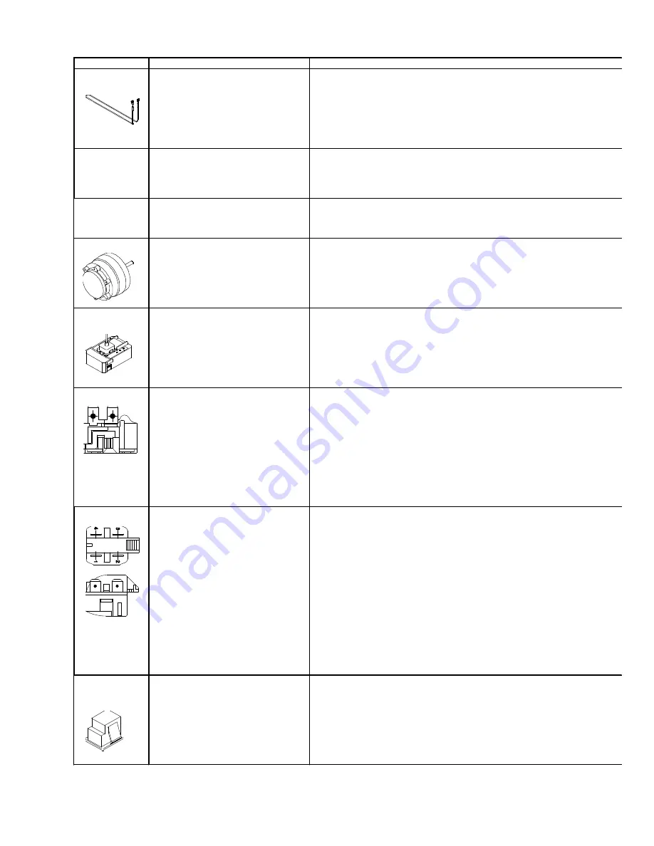
Motor, condenser
Condenser fan moves cooling air across
condenser coil and compressor body.
Condenser fan motor is in parallel circuit
with compressor.
Check resistance across coil.
Motor,
evaporator fan
Evaporator fan moves air across
evaporator coil and throughout
refrigerator cabinet.
Evaporator fan is in a series circuit with
temperature control, defrost terminator,
and defrost heater.
1.
Disconnect power to unit.
2.
Disconnect fan motor leads.
3.
Check resistance from ground connection solder. Trace to motor frame
must not exceed .05 ohms.
4.
Check for voltage at connector to motor with terminator and temperature
control closed.
Overload
Overload is a temperature and current
sensing device.
Overload opens when high current or
high compressor temperature is sensed.
After overload opens, reset can require
up to two hours depending on ambient
temperature and residual heat load in
compressor.
Relay (See PTC Relay)
1.
Disconnect power to the refrigerator.
2.
Remove relay cover and pull relay off compressor. Pull overload protector
off compressor common terminal.
3.
With ohmmeter, check resistance between male terminal and female pin
receptacle terminal which pushes onto compressor common terminal. At
ambient room temperature overload protector should have less than 1 ohm
resistance. An open overload protector will have infinite resistance.
Relay, PTC
When voltage is connected and relay is
cool, current passes through relay to
start winding.
After a short time, current heats the
resistor in relay and resistance will rise
blocking current flow through relay.
Start winding remains in the circuit
through run capacitor.
Solid state relay plugs directly on
compressor start and run terminals.
Relay terminals 2 and 3 are connected
within relay. Run capacitor is connected
to relay terminal 3. L2 side of 230 VAC
power is connected to relay terminal 2.
1.
Disconnect power to the refrigerator.
2.
Remove relay cover and disconnect leads.
3.
Check resistance across terminals 2 and 3 with an ohmmeter:
Normal = 3 to 12 ohms
Shorted = 0 ohms
Open = infinite ohms
Switch,
refrigerator light,
freezer light
Single pole, single throw switch
completes circuit for light when door is
open.
Check resistant across terminals.
Switch arm depressed
“NO” terminals
Open
Switch arm up
“NO” terminals
Closed


