background image

21

RS5280001  Rev. 0

Symptom

Possible Causes

Corrective Action

Defrost thermostat faulty

Check defrost thermostat. Replace if
defective.

Evaporator fan faulty

Check fan motor. Replace if
defective.

Defrost heater remains open

Check defrost heater continuity.
Replace if defective.

Defrost control faulty

Check control and replace if
defective.

Open wire or connector

Check wiring and connections.
Repair as necessary.

Frost or ice on evaporator

Refrigerant shortage or restriction

Check for leak or restriction. Repair,
evacuate and recharge system.

Loose wire or thermostat
connections

Check wiring and connections.
Repair as necessary.

Supply voltage out of specification

Check input voltage. Correct any
supply problems.

Overload protector open

Check overload protector for
continuity. If open, replace overload.

NOTE:

 Ensure

overload/compressor are below
trip temperature before testing.

Faulty compressor motor capacitor

Check capacitor for open/short.
Replace if necessary.

NOTE:

 Discharge capacitor

before testing.

Faulty fan motor

Check fan motor. Replace if
defective.

Restricted air flow

Check condenser and grille for dirt.
Clean.

Unit starts and stops frequently
(cycles on and off)

Refrigerant shortage or restriction

Check for leak or restriction. Repair,
evacuate and recharge system.

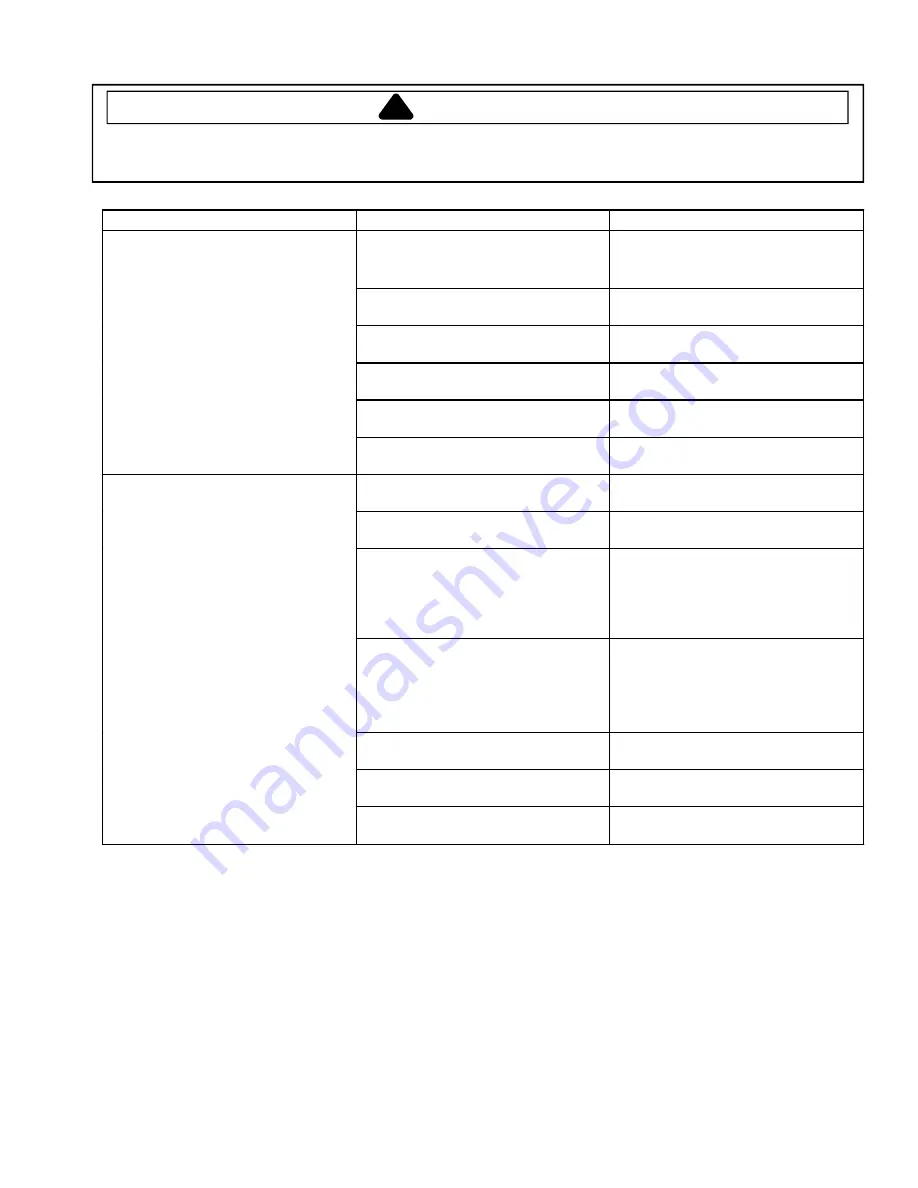
Troubleshooting Chart

To avoid risk of electrical shock, personal injury, or death, disconnect electrical power source to unit, unless test
procedures require power to be connected. Discharge capacitor through a 10,000 ohm resistor before attempting
to service. Ensure all earthing wires are connected before certifying unit as repaired and/or operational.

!

WARNING

Содержание ATX 518 VW

Страница 1: ...esponsibility for property damage or personal injury for improper service procedures done by an unqualified person RS5280001 Revision 0 September 2001 V Model International Top Mount Refrigerators Models and manufacturing numbers in this manual ATX 518 VW P1322503W W HT600W P1322901W W TR521VW P1322601W W TR525VW P1322701W W TW518VW P1322501W W TX518VW P1322502W W ...

Страница 2: ...amage from improper service procedures If preforming service on your own product assume responsibility for any personal injury or property damage which may result To locate an authorized servicer please consult your telephone book or the dealer from whom you purchased this product For further assistance please contact CONSUMER AFFAIRS DEPT OR 1 319 622 5511 or 1 800 843 0304 AMANA REFRIGERATION IN...

Страница 3: ...et 40 Inner Door 40 Cabinet Components 40 Refrigerator Control Housing 40 Refrigerator Damper Control 40 Freezer Temperature Control 40 Defrost Timer 40 Moisture Control Heater Switch 41 Refrigerator Light Switch 41 Center Mullion 41 Light Lens and Light Bulbs 41 Refrigerator Light Socket 41 Freezer Wire Shelf and Shelf Retainers 41 Freezer Basket Slide Retainer 41 Freezer Light Reflector and Sock...

Страница 4: ...RS5280001 Rev 0 4 Table of Contents Kit Instructions DT17 DT18 and DT19 Kits 55 DT14 And DT15 1 4 Top Freezer Refrigerator Trim Kit 57 TDMK14AndTDMK15 Top Freezer Refrigerator Trim Kits 63 ...

Страница 5: ... Power Cord Electrical Rating 250 V 16A Service Keep a copy of sales receipt for future reference or in case warranty service is required Any questions or to locate an authorized servicer call 1 800 NAT LSVC 1 800 628 5782 inside U S A 319 622 5511 outside U S A Warranty service must be performed by an authorized servicer Amana also recommends contacting an authorized servicer if service is requir...

Страница 6: ...connection proceed to Connect Ice Maker Water Supply section before leveling your refrigerator 1 Plug in power cord 2 Move refrigerator into final location 3 Level refrigerator using a level placed on top of the refrigerator Remove toe grille Remove bottom hinge cover if refrigerator has a stabilizing leg Turn hex head roller adjustment screws to raise or lower refrigerator cabinet Front of refrig...

Страница 7: ... D Center hinge pin E Center hinge bracket F Phillips screws G 3 8 screws H Bottom hinge I Center hinge J Top hinge Hinges 9 Reverse doors by performing the following steps Replace bottom hinge and shim on opposite side of cabinet Remove button plugs from center mullion Place button plugs in holes left when center hinge bracket was removed Rotate center hinge bracket 180 and install center hinge b...

Страница 8: ...ng leg is raised before moving refrigerator Raise stabilizing leg by turning counterclockwise CAUTION Observe the following to avoid property damage Confirm water pressure to water valve is between 1 37and 6 89 bar Copper supply tubing must be routed where the temperature is 55 F 13 C or higher to prevent freeze ups Start adaptor fitting and nuts by hand to avoid cross threading Tighten adaptor fi...

Страница 9: ...sh Food nor Deepfreeze sections will cool Initially set both controls to 4 Wait 24 hours for Fresh Food and Deepfreeze sections to reach desired temperatures After 24 hours adjust controls one number at a time as desired 1 is warmest setting and 7 is coldest Setting Controls Set controls precisely with a household thermometer that includes temperatures between 5 to 50 F 21 to 10 C Put thermometer ...

Страница 10: ... system features a drawer inside a sleeve Air circulates between drawer and sleeve This system keeps food fresh longer and up to 5 F 3 C colder than Fresh Food temperature Chiller Fresh control is located below front shelf trim Control adjusts amount of air circulating around drawer Slide control to cold for normal Fresh Food temperature and to coldest for colder temperature Ice crystals may form ...

Страница 11: ...ully Shelves may break suddenly if nicked scratched or exposed to sudden temperature change 2 Remove shelf by gently pushing up from underneath Tilt one end up then pull out B A A Crisper shelf B Push shelf up Garden fresh crisper 3 Remove left crisper by lifting front while supporting underneath then pulling out For doors hinged on left remove right crisper 4 Remove support post at recess in bott...

Страница 12: ...om can be used as an additional door bucket Remove snaccess bin by lifting door pushing tabs toward center and pulling out Replace snaccess bin by sliding in until tabs lock into place and lowering door A A Snaccess bin door Snaccess bin removal Door Buckets Door buckets adjust to meet individual storage needs Remove door buckets by pushing tabs toward center and pulling out Replace door buckets b...

Страница 13: ...ng ice production ice maker arm raises and lowers When ice storage bucket is full ice maker arm turns ice maker off Discard first 3 harvests of ice after initially connecting refrigerator to household water supply and after extended periods of non use Stop ice production by raising ice maker arm A definite click is heard when proper position is reached Ice maker arm will remain in that position un...

Страница 14: ...k Ice service rack Wire Shelf Remove wire shelf by tilting one end up and pulling out Replace wire shelf by tilting one end up and placing end on ledge Tilt other end down and place on ledge Wire shelf Wire Rack Some models Wire rack provides space saving storage above or below wire shelf Remove rack by releasing round knobs from shelf wires Pull down if located under shelf or lift up if located a...

Страница 15: ...ace garden fresh crispers on top shelf of Fresh Food section Pack Fresh Food and Deepfreeze sections including doors with crumpled sheets of black and white newspaper 6 Place charcoal briquettes randomly throughout newspaper 7 Close doors and let stand 24 48 hours 8 Remove charcoal briquettes and newspapers 9 Complete steps 2 3 Contact your Distributor if odor was still not eliminated or call 001 ...

Страница 16: ... back center Pull cover down Replace bulb s with 40 watt appliance bulb s Replace light bulb cover by placing cover over light bulb Insert and tighten screw Light bulb Energy Tips This refrigerator is designed to be one of the most energy efficient refrigerators available Reduce energy use by observing the following Operate in normal household temperatures of 55 to 110 F 13 to 43 C away from heat ...

Страница 17: ... for recently added warm food to reach Fresh Food or Deepfreeze temperature Clean condenser coils Adjust Deepfreeze control Check gaskets for proper seal Water droplets form on inside of refrigerator It is normal during high humidity periods or if doors have been opened frequently Water droplets form on outside of refrigerator Check door gaskets for proper seal Turn exterior moisture control switc...

Страница 18: ...inserted into proper holes Check for kinks in copper or plastic tubing Remove kinks or replace tubing Check electrical connections to water valve coil and connector block on refrigerator cabinet Confirm Deepfreeze section is operating at proper temperature Ice cubes have an odor See Odor Removal instructions in Care and Cleaning section Discard ice and clean ice bucket or trays more frequently Ice...

Страница 19: ...education Overloading of shelves Consumer education Warm or hot foods placed in cabinet Consumer education Cold control set too warm Set control to colder setting Poor door seal Level cabinet Adjust hinges Replace gasket Refrigerator airflow Check damper is opening by removing grille With door open damper should open Replace if faulty Turn control knob to colder position Check airflow fan Replace ...

Страница 20: ...triction Repair evacuate and recharge system Refrigerant overcharge Check for overcharge Evacuate and recharge system Unit runs continuously Air in system Check for low side leak Repair evacuate and recharge system Unit runs continuously Temperature normal Ice on evaporator See Ice on evaporator Unit runs continuously Temperature too cold Faulty defrost thermostat Check thermostat Replace if neces...

Страница 21: ...load protector open Check overload protector for continuity If open replace overload NOTE Ensure overload compressor are below trip temperature before testing Faulty compressor motor capacitor Check capacitor for open short Replace if necessary NOTE Discharge capacitor before testing Faulty fan motor Check fan motor Replace if defective Restricted air flow Check condenser and grille for dirt Clean...

Страница 22: ...on from Normal Wattage Variation from Normal Refrigerant Overcharge Increase Increase Warmer Warmer Colder Increase Refrigerant Shortage Decrease Decrease or Increase Restriction Symptoms Colder Warmer Warmer Decrease Partial Restriction Decrease Decrease or Increase Restriction Symptoms Colder Warmer Warmer Decrease Air in system Near Normal Increase Warmer Warmer Warmer Increase Low Ambient Inst...

Страница 23: ...ace capacitor High resistance leak needle jumps toward 0 and then moves back to constant high resistance not infinity Capillary tube Capillary is sized in diameter and length to feed proper amount of refrigerant to evaporator Capillary is soldered to suction line to transfer heat from capillary and add additional superheat to gas refrigerant in compressor suction line Capillary discharges into eva...

Страница 24: ... to compressor body clean point of contact and other probe to each compressor terminal If reading is obtained compressor is grounded and must be replaced Operation test If voltage capacitor overload and motor winding tests do not show cause for failure perform the following test 1 Disconnect power to refrigerator 2 Discharge capacitor by shorting capacitor terminals through a resistor 3 Remove lea...

Страница 25: ...tion line Leaks in condenser can usually be detected by using an electronic leak detector or soap solution Look for signs of compressor oil when checking for leaks A certain amount of compressor oil is circulated with refrigerant Leaks in post condenser loop are rare because loop is a one piece copper tube For minute leaks 1 Separate condenser from rest of refrigeration system and pressurize conde...

Страница 26: ...to drier and break 2 Reform inlet tube to drier allowing enough space for large tube cutter 3 Cut circumference of drier 31 75 mm below condenser inlet tube joint to drier 4 Remove drier 5 Apply heat trap paste on post condenser tubes to protect grommets from high heat 6 Unbraze remaining part of drier Remove drier from system 7 Discard drier in safe place Do not leave drier with customer If refri...

Страница 27: ...verload is a temperature and current sensing device Overload opens when high current or high compressor temperature is sensed After overload opens reset can require up to two hours depending on ambient temperature and residual heat load in compressor Relay See PTC Relay 1 Disconnect power to the refrigerator 2 Remove relay cover and pull relay off compressor Pull overload protector off compressor ...

Страница 28: ... coil below freezing thermostat should show continuity when checked with ohmmeter See Heater evaporator defrost section for additional tests Timer defrost Timer motor operates only when freezer control is closed After specified amount of actual operating time inner cam in timer throws the contacts from terminal 4 compressor circuit to terminal 2 defrost thermostat defrost heater circuit After spec...

Страница 29: ... system Equipment must be exclusively used for HFC134a Exclusive use of equipment only applies to italic items Evacuation pump Check with vacuum pump supplier to verify equipment is compatible for HFC134a Robinair Model 15600 2 stage 6 cubic feet per minute pump is recommended Four way manifold gauge set with low loss hoses Leak detector Charging cylinder Line piercing saddle valve Schroeder valve...

Страница 30: ...ad on test cord attaches to M terminal on compressor Service Procedures C R S Fuses Capacitor Compressor Switch To AC supply Attaching Capacitor for Compressor Test 5 Connect a known good capacitor into circuit as shown above For proper capacitor size and rating see technical data sheet for unit under test NOTE Ensure test cord cables and fuses meet specifications for unit under test see Technical...

Страница 31: ...s are best detected with halide or electronic leak detectors Testing Systems Containing a Refrigerant Charge 1 Stop unit operation turn refrigerator off 2 Holding leak detector exploring tube as close to system tubing as possible check all piping joints and fittings NOTE Use soap suds on areas leak detector cannot reach or reliably test Testing Systems Containing No Refrigerant Charge 1 Connect cy...

Страница 32: ...pressure and wattage while low side is being pumped out Testing for Restrictions To determine if a restriction exists 1 Attach gauge and manifold between suction and discharge sides of sealed system 2 Turn unit on and allow pressure on each side to stabilize Inspect condenser side of system Tubing on condenser should be warm and temperature should be equal throughout no sudden drops at any point a...

Страница 33: ...all other valves and start vacuum pump Vacuum Pump 6 cm Copper Tubing Compressor Compressor Process Tube Charging Hose Thermistor Vacuum Gauge Low Side Gauge E Valve B D Valve High Side Gauge Charging Hose Drier Process Tube F Valve Charging Cylinder C A Equipment Setup For Evacuation And Charging 5 After compound gauge low side drops to approximately 29 inches gauge open valve C to vacuum thermoc...

Страница 34: ...5 Start compressor and draw remaining refrigerant from charging hoses and manifold into compressor through compressor process tube 6 To check high side pinch off drier process tube Close valve D to high side gauge If high side pressure rises repeat high side pinch off and open valve D Repeat until high side pinch off does not leak 7 Pinch off compressor process tube and remove charging hose Braze ...

Страница 35: ...ce Information HFC134a is alternative refrigerant for CFC12 HFC134a has an ozone depletion potential ODP factor of 0 0 and a global warming potential GWP factor of 0 27 HFC134a is not flammable and has acceptable toxicity levels HFC134a is not interchangeable with CFC12 There are significant differences between HFC134a and CFC12 which must be considered when handling and processing refrigeration s...

Страница 36: ... and Relationship Chart Normally these are not required for diagnosis but used for confirmation on systems which have been opened Service Procedures To avoid risk of electrical shock personal injury or death disconnect electrical power source to unit unless test procedures require power to be connected Discharge capacitor through a 10 000 ohm resistor before attempting to service Ensure all earthi...

Страница 37: ...37 RS5280001 Rev 0 Refrigerant Flow V Model Top Mount Refrigerant Flow Diagram EVAPORATOR SUCTION TUBE CAPILLARY TUBE PROCESS TUBE DRIER CONDENSER COMPRESSOR DISCHARGE TUBE SUBCOOLER ...

Страница 38: ...RS5280001 Rev 0 38 Cabinet Air Flow V Model Top Mount Air Flow Diagram EVAPORATOR FREEZER AIR RETURN FRESH FOOD AIR SUPPLY CONDENSER FAN ASSEMBLY CONDENSER COMPRESSOR FRESH FOOD AIR RETURN ...

Страница 39: ...eat Pattern 3 3 SIDE FRONT SIDE TOP BACK BOTTOM FREEZER DOOR CENTER MULLION TOP REFRIGERATOR DOOR BOTTOM REFRIGERATOR DOOR LOWER MULLION CLASSIFICATIONS OF CONDENSATION 1 Haze or Fog 2 Beading 3 Beads or Small Drops 4 Drops Running Together ...

Страница 40: ...using unclip and lift control from mounting post 2 Remove gasket material and electrical wiring tape securing capillary to control housing Unclip capillary NOTE Before installing control rotate control shaft to most counterclockwise position Install rack slide in far right position to synchronize with damper setting NOTE In reassembly verify the capillary is clipped in place and taped to control h...

Страница 41: ...uver shelf around retainers and pull wire shelves out from retainers 2 Pull baskets out of retainers Freezer Basket Slide Retainer Remove two mounting screws and remove retainer Freezer Light Reflector and Socket 1 Remove lens 2 Remove three screws holding light reflector at front 3 Slide reflector toward front until rear of reflector is free of freezer liner Remove wiring leads 4 Socket snaps out...

Страница 42: ...il and 2 from right side 3 Remove defrost thermostat 4 Remove defrost heater by removing wire clips hold heater to bottom of evaporator coils Remove heat exchanger and machine compartment covers 5 Shield interior from heat source and unbraze suction tube at compressor 6 Score and break capillary tube at drier 7 Straighten heat exchanger and pull evaporator out of plastic clips holding it to back w...

Страница 43: ...towards outside of cabinet and out of rail Water Valve 1 Remove machine compartment cover and heat exchanger cover on rear of unit 2 Disconnect water supply 3 Remove brass nuts at water valve inlet and outlet 4 Pull copper tubing from water valve Anti kink springs are installed in plastic tubing connecting to valve Machine Compartment 1 Remove machine compartment cover on rear of unit and heat exc...

Страница 44: ...wire harness from condenser fan shroud and drier filter from metal clip 6 Capture refrigerant charge 7 Remove hex head shoulder bolts mounting compressor to machine compartment floor 8 Unbraze suction and discharge tubing from compressor 9 Remove ground wire screw to compressor 1 Remove compressor compartment rear cover and heat exchanger cover 2 Remove two screws securing condenser fan shroud to ...

Страница 45: ...E Condenser is only available as assembly with base pan 3 Unbraze compressor from condenser and unbolt compressor from base pan and partially remove 4 Remove base pan from unit and remove the condenser fan motor shroud condensate drain pan capacitor and wiring harness Remount these components during reassembly Drain Tube and Drain Elbow 1 Remove machine compartment rear cover and heat exchanger co...

Страница 46: ... N M H T L V Specifications Mold Heater 185 Watts 264 Ohms Thermostat Close 8 1 C 17 3 F Bimetal Opens 0 1 C 17 3 F WaterFill 140 cc 7 5 Sec Motor Cycle Stamped in Circuit Plug in Connectors One Revolution of blades take three minutes plug stall time on ice Eject and Water Fill Testing Procedures Ice maker plugged into power shut off arm down freezer cold 1 Test point L and N will verify 230 volts...

Страница 47: ...Note knob position and reinstall in same position for same water fill To avoid possible electrical shock always turn off power before beginning any disassembly Module Motor and Support Assembly Insert phillips driver in access ports in module Loosen both screws Disconnect shut off arm Pull mold from support assembly To remove module only remove three phillips screws and pull module out of housing ...

Страница 48: ...tor is defective it will run The shut off arm must be in the on position NOTE There are several slotted shafts on the motor assembly board Do not under any circum stances insert a screwdriver and attempt to turn these shafts The slots are to permit as sembly only NOTE There are not repairable or replaceable components in the module Unless you are replacing the module there should be no need to rem...

Страница 49: ...tes and sediment filter Part Number R0183114 Mineral contact can also lime up the mold causing wicking of water over the mold and poor cube release Silicone is applied at the upper edges around fill cup and stripper Temperature Problems Temperatures in freezer section which average above the normal 18 1 C 0 2 F will slow production of ice Complaints of inadequate ice cube production may be correct...

Страница 50: ...f wa ter allowed to enter ice maker mold is directly propor tional to the length of time the water valve switch is held closed by the timing cam Inside the valve is a flow washer which acts as a water pressure regulator Proper ice maker fill is 140 cc 10 cc at 7 5 seconds of water fill at an inlet pressure ranging from 1 4 to 8 2 bar 20 to 120 PSI When the light blue encapsulated solenoid is ener ...

Страница 51: ...ter Pressure NOTE Jump Cycle through T H Probe holes for 10 Sec Then Remove Jumpers Catch Water in Glass f Water Pressure Must Be Increased 20 120 psi 1 4 8 2 bar Should be About 140 cc s g Open Heater Circuit g Change Mold and Heater Assembly h Closed Thermostat h Change Thermostat i Damaged Heater Tulips on Module i Change Module j Heater Pins Too Short Not Contacting Module j Change Mold Heater...

Страница 52: ...Oscillating 3 Change Mold Heater Assy Apply Fresh Coat Of Alumilastic 4 Little No Alumilastic on Thermostat 4 Apply Fresh Coat Of Alumilastic 5 Heater Not Staked In Mold 5 Change Mold Heater Assy Apply Fresh Coat Of Alumilastic 6 Broken Locking Tabs on Vertical Cam 6 Change Module D 6 00 Ejector Position 1 Contamination 1 Change Ice Maker Module 2 Hollow Cubes 2 Refer to Section III Hollow Cubes 3...

Страница 53: ... Apply Fresh Alumilastic 2 Jammed Cube Stalled In Water Fill Cycle 2 Remove Cube Determine Reason For Stall 3 Leaky Water Valve 3 Change Water Valve 4 Fill Volume of Water Valve Excessive 4 Change Water Valve 5 Motor Stalled In Water Fill Cycle 12 00 Ejector Position 5 Change Ice Maker Module 6 Contaminated Module 6 Change Ice Maker Module 7 Refrigerator or Ice Maker Not Level 7 Level As Necessary...

Страница 54: ...RS5280001 Rev 0 54 Ice Maker Wiring Diagram and Parts Layout 230 ...

Страница 55: ... solve a problem during installation contact source from whom kit was purchased Decorator Panel Dimensions Listed below are required height x width dimensions for decorator panels Panels are not supplied with this kit and can be purchased locally If panels are less than 1 4 inch 6 millimeters thick spacers are required behind panels If panels are more than 1 4 inch 6 millimeters thick panel edges ...

Страница 56: ...ed tape is used to attach trim Before removing paper backing check placement of trim on door Trim may be damaged if adjustment or removal is attempted after installation Remove paper backing from bottom trim and press trim firmly to bottom of door 15 Place door stop on door bottom Insert and tighten screws with a Phillips screwdriver Insert and tighten screws on opposite side of door with a Philli...

Страница 57: ...ust be clean dry and free of adhesive residue before installing trim kit PARTS LIST Refer to item number on the parts list for description part number and quantity NOTE Use only supplied parts Check the kit to be sure all parts are included before starting installation If parts are missing contact the local Amana dealer Part numbers are not used in installation instructions Use parts list only for...

Страница 58: ...ms Trim pieces may have sharp edges Installation Procedure NOTE The 6 35 mm trim kit fits only a refrigerator freezer in which a 3 175 mm trim kit has been installed Install a 3 175 mm trim kit before proceeding 1 Removerefrigeratorandfreezerdoorhandles A Using a taped small flat blade screwdriver lift rear of screw caps on both doors B On both doors remove screws from top and bottom of each handl...

Страница 59: ...frontofrefrigeratordoor A To prevent scratching refrigerator door when sliding panel into trim slots cover outside edges of rear panel surface with masking tape and put six 6 evenly spaced strips of masking tape across the rear side of the decorator panel B Slide decorator panel into place IMPORTANT Permanent type double sided adhesive tape is attached to all trim pieces for easy installation Befo...

Страница 60: ... check the fit of the trim pieces and be sure you understand how to install each one Damage to trim pieces could result if adjustment or removal is attempted after installation 7 Remove handle left side freezer trim carefully using a taped putty knife 8 Install the handle left side 6 35 mm trim on pre cut freezerpanel A Be sure front surface of trim piece faces decora tor surface of pre cut panel ...

Страница 61: ... of the decorator panel B Slide decorator panel into place IMPORTANT Permanent type double sided adhesive tape is attached to all trim pieces for easy installation Before peeling away paper backing from tape check the fit of the trim pieces and be sure you understand how to install each one Damage to trim pieces could result if adjustment or removal is attempted after installation 10 Attach handle...

Страница 62: ...RS5280001 Rev 0 62 Kit Instructions 11 Re attach freezer door handle A Secure screws on side and bottom of handle B Re install screw cap cover by snapping into place ...

Страница 63: ...ption part number and quantity NOTE Use only supplied parts Check the kit to be sure all parts are included before starting installation If parts are missing contact the local Amana dealer Part numbers are not used in installation instructions Use parts list only for ordering 3 175 MM Trim Kit Model No TDMK 14 for 510 and 538 Liter Units PART ITEM DESCRIPTION NUMBER QTY 1 Bottom Freezer Door Trim ...

Страница 64: ...2 9 32 x 41 3 4 81 99 cm x 106 05 cm Recommended Tools To install the 3 175 mm trim kit and panels use the following basic tools Phillips screwdriver Hex head nutdriver small flat blade screwdriver strapping safety tape tightly fitting gloves and arm protection To avoid possible injury protect hands and arms Trimpiecesmayhavesharpedges NOTE Hinges for each model may appear slightly different than ...

Страница 65: ...e pin A Use hex head nutdriver to loosen screws B Release center hinge pin by pulling it straight up with holding refrigerator door closed Plastic spacer should remain with center hinge pin C Center hinge bracket must remain attached to refrigerator 5 Remove refrigerator door A Remove strapping tape B As door is opened tilt top edge out and lift door upward C Bottom hinge bracket hinge pin and pla...

Страница 66: ...sy installation Before peeling away paper backing from tape check the fit of the trim pieces and be sure you understand how to install each one Damage to trim pieces could result if adjustment or removal is attempted after installation 9 Remove any existing top refrigerator door trim Trim may be held in place with screws or with adhe sive Use extreme care to gently pull trim away from door 10 Inst...

Страница 67: ...djustment or removal is attempted after installation 13 Install trim on refrigerator door bottom A Before removing paper backing from adhesive check the fit by aligning trim snugly on bottom of refrigerator door B Align screw holes C Remove paper backing from adhesive on trim and press into place D On the side of the door opposite the hinge use two 2 Phillips screws to secure trim 14 Re installref...

Страница 68: ...r IMPORTANT If a 6 35 mm trim kit is to be installed turn NOW to STEP 3 in the 6 35 mm Trim Kit Instructions to finish installation Proceed with Step 17 below only if the 3 175 mm trim kit is to be installed alone 17 Install decorator panel on front of refrigerator door A To prevent scratching refrigerator door when sliding panel into trim slots cover outside edges of rear panel surface with maski...

Страница 69: ...tape C Press handle left side trim into place over the edges of trim on top and bottom of door 19 Re attach refrigerator door handle A Secure screws on top and side of handle B Re install screw cap cover by snapping into place 20 Install refrigerator side trim hole plug supplied with kit ...

Страница 70: ...n bottom of freezer door B Align screw holes C Remove paper backing from adhesive on trim and press into place 23 Re install freezer door stop using a Phillips screw driver to secure door stop by replacing the two 2 screws 24 Install trim on freezer door top A Before removing paper backing from adhesive check the fit by aligning trim snugly on top of freezer door Top trim must be tucked under side...

Страница 71: ...Trim Kit Instructions to finish installation Proceed with Step 28 below only if the 3 175 mm trim kit is to be installed alone 28 Install decorator panel on front of freezer door A To prevent scratching freezer door when sliding panel into trim slots cover outside edges of rear panel surface with masking tape and put three 3 evenly spacedstripsofmaskingtapeacross the rear side of decorator panel B...

Страница 72: ... 30 Re attach freezer door handle A Secure screws on bottom and side of handle B Re install screw cap cover by snapping into place 31 Install freezer side trim hole plug supplied with kit Installation of 3 175 mm trim kit is now complete ...

Отзывы: