


4
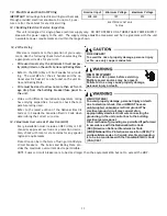
5.4 Clearances
The unit clearance from a combustible surface may be 0". However, service clearance must take precedence. A
minimum of 24" in front of the unit for service clearance is required. Additional clearance on one side or top will be
required for electrical wiring connections. Consult all appropriate regulatory codes prior to determining final clear-
ances. When installing this unit in an area that may become wet (such as crawl spaces), elevate the unit with a
sturdy, non-porous material. In installations that may lead to physical damage (i.e. a garage) it is advised to install
a protective barrier to prevent such damage. Always install units such that a positive slope in condensate line (1/4"
per foot) is allowed.
5.5 Horizontal Applications
If installed above a finished living space, a secondary drain pan (as required by many building codes), must be
installed under the entire unit and its condensate drain line must be routed to a location such that the user will see
the condensate discharge.
6 Installation Location
NOTE:
These air handlers are designed for
indoor installation
only
.
The ARUF**14** and ASPT**14** product lines may be installed in
one of the upflow, downflow, horizontal left or horizontal right
orientations as shown in Figures 2, 3, 4 and 5. The unit may be
installed in upflow or horizontal left orientation as shipped (re-
fer to specific sections for more information).
Minor field modifications are necessary to convert to downflow
or horizontal right as indicated in below sections.
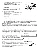
Side Drain Pan Removal:
Refer to Figure 1, remove the two (2)
screws that secure the drip shield support brackets to the
condensate collectors (front and back). Unsnap the side drain
pan from vertical (bottom) drain pan using a screw driver or any
small lever. The side drain pan and drip shield brackets may now
be removed. The bottom left drain connection is the primary
drain for this application and condensate drain line must be
attached to this drain connection. The bottom right drain
connection is for the secondary drain line (if used).
6.1 Upflow Installation
No field modifications are mandatory however to obtain maxi-
mum efficiency, the horizontal side drain pan & extension must
be removed.
6.2 Horizontal Left Installation
No field modifications are permissible for this application.
The bottom left drain connection is the primary drain for this application and condensate drain line must be attached to
this drain connection. The bottom right drain connection is
for the secondary drain line (if used).
6.3 Downflow
No field modifications are mandatory however to obtain
maximum efficiency, the horizontal side drainpan & exten-
sion must be removed.
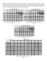
IMPORTANT NOTE:
To prevent coil pan “sweating” in the
downflow application, a downflow kit (DFK) is available
through your local distributor. The DFK is not supplied with
the air handler and is required by the manufacturer on all
downflow installations. See Table 1 for the correct DFK and
follow the instructions provided for installation.
DRIP SHIELD REMOVAL
Figure 1
DOWNFLOW KIT
Table 1
DFK-B
DFK-C
DFK-D
DOWNFLOW KIT
DOWNFLOW KIT
DOWNFLOW KIT
ARUF25B14**
ARUF37C14**
ARUF37D14**
ARUF29B14**
ARUF43C14**
ARUF43D14**
ARUF31B14**
ARUF49C14**
ARUF47D14**
ARUF49D14**
ARUF61D14**
ASPT61D14**
MODEL LIST FOR DOWNFLOW KIT
Содержание ARUF**14 Series
Страница 19: ...19 THIS PAGE LEFT INTENTIONALLY BLANK ...


