


12
12.4 Electrical Connections – Supply Voltage
IMPORTANT NOTE: USE COPPER CONDUCTORS ONLY.
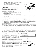
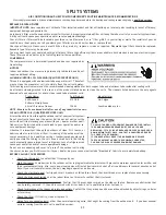
Knockouts are provided on the air handler top panel and
sides of the cabinet to allow for the entry of the supply
voltage conductors, as shown in Figure 13. If the knockouts
on the cabinet sides are used for electrical conduit, an
adapter ring must be used in order to meet UL1995 safety
requirements. An NEC or CEC approved strain relief is to be
used at this entry point. Some codes/municipalities re-
quire the supply wire to be enclosed in conduit. Consult
your local codes.
12.4.1 Air Handler Only (Non-Heat Kit Models)
The building supply connects to the stripped black and red
wires contained in the air handler electrical compartment
cavity. A ground screw is also contained in this area. At-
tach the Supply wires to the air handler conductors as shown in the unit wiring diagram using appropriately sized
solderless connectors or other NEC or CEC approved means.
12.4.2 Air Handler - Non-Circuit Breaker Heat Kits
A terminal block is provided with the HKS kit to attach the power supply and air handler connections. Follow the
HKS Installation Manual and wiring diagram for complete wiring details.
12.4.3 Air Handler With Circuit Breaker Heat Kit
The air handler has a plastic cover on the upper access panel that will require either one or both sections to be
removed to allow the heat kit circuit breaker(s) to be installed. The circuit breakers have lugs for power supply
connection. See the HKS Installation Instructions for further details.
12.5 Low Voltage Connections
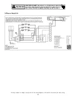
Several combinations of low voltage schemes are possible, depending on the presence of a heat kit and whether the
heat kit is single-stage or multi-stage, whether the outdoor section is an air conditioner or heat pump, and whether
the outdoor section is single-stage or two-stage. The 24V-control voltage connects the air handler to the room
thermostat and condenser. Low voltage wiring must be copper conductors. A minimum of 18AWG must be used for
installations up to 100 feet. Low voltage wiring must be connected through the top of the cabinet or either side.
See the “Thermostat Wiring” section of this manual for typical low voltage wiring connections.
12.5.1 Thermostats
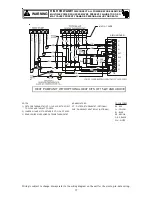
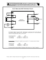
Second-stage heat can be accomplished by a multi-stage heating thermostat or the addition of an outdoor thermo-
stat as shown in wiring schematics on pages 14 and 15. Follow the thermostat manufacturer’s instructions for
installation.
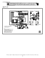
12.6 Speed Tap Adjustment
ARUF**14** air handlers have multi-speed PSC motors. The color of the wire coming from the motor to the “COM”
terminal on the control board defines at which speed the motor will operate. Black wire is high speed, blue wire is
medium speed and red wire is low speed. To change speeds, remove the wire attached to the “COM” terminal on
the control board, and swap it with the wire (on terminal “M1” or “M2”) with the color that will give the desired
speed.
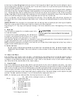
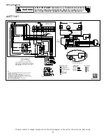
ASPT**14** air handlers feature energy efficient blower motors. The motors run at a constant torque with very low
power consumption and are energized by 24 VAC. Adjust the CFM by changing the 24 VAC leads to the desired speed
tap on the terminal block. The ASPT blower motor speeds are programmed to deliver adequate airflow at rated
external static pressure and with 60 second off time delay. For details, refer to the specification sheet applicable
to your model.
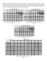
NOTE:
In some models, not all speed taps are allowable for certain electric heat applications. Refer to Table 5 for
minimum speed.
Side of
Cabinet
Top of
Cabinet
KNOCK-OUT FOR ELECTRICAL CONNECTIONS
Figure 13
Содержание ARUF**14 Series
Страница 19: ...19 THIS PAGE LEFT INTENTIONALLY BLANK ...


