


18
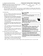
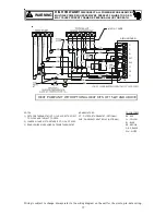
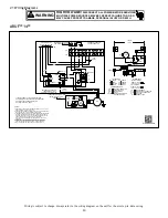
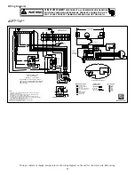
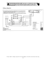
Wiring is subject to change. Always refer to the wiring diagram on the unit for the most up-to-date wiring.
HIGH VOLTAGE!
DISCONNECT ALL POWER BEFORE SERVICING.
MULTIPLE POWER SOURCES MAY BE PRESENT. FAILURE TO DO SO
MAY CAUSE PROPERTY DAMAGE, PERSONAL INJURY OR DEATH.
WARNING
120/240VAC
TSTAT
OPTIONAL
SPEEDUP
24 VAC
SYSTEM
TRANSFORMER
C
SPEEDUP
XFMR-C
XFMR-R
R
B13707-35
WIRING DIAGRAM
M1
PARK TERMINAL
K1
K1
FOR USE WITH
NEUTRAL
G
HEAT KIT
MOTOR
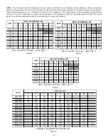
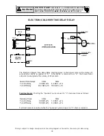
The Electronic Blower Time Delay Relay provides power to the blower motor with a delay of 7
seconds after 24VAC is applied to “G”. After 24VAC is removed from “G”, the blower motor
output is de-energized after a delay of 65 seconds.
Normal Time Delays
60Hz
50Hz
Turn On Delay
7.0 SEC.±1%
8.4 SEC. .±1%
Turn Off Delay
65.0 SEC.±1%
78.0 SEC. .±1%
Field test mode:
Shorting the “speedup” quick connect to “C” decrease times as follows:
Speedup Times
60Hz
50Hz
Turn On Delay
3.0 SEC.±1%
3.6 SEC. .±1%
Turn Off Delay
5.0 SEC.±1%
6.0 SEC. .±1%
Field test mode is cancelled when the “speedup” quick connect to “C” short is removed.
ELECTRONIC BLOWER TIME DELAY RELAY
Содержание ARUF**14 Series
Страница 19: ...19 THIS PAGE LEFT INTENTIONALLY BLANK ...


