15
With Power And Gas On:
3. Put unit into heating cycle and turn on all other gas
consuming appliances.
Natural
Min. 5.0" W.C., Max. 10.0" W.C.
Propane
Min. 11.0" W.C., Max. 13.0" W.C.
INLET GAS PRESSURE
NOTE:
Inlet gas pressure be within the minimum and maxi-
mum value shown. If operating pressures differ from above,
make necessary pressure regulator adjustments, check pip-
ing size, etc., and/or consult with local utility.
4. Turn off all electrical power and gas supply to the
system.
5. Remove manometer hose from the outlet pressure
boss (or remove hose from hose barb).
6. Turn inlet pressure test screw in to seal pressure port
(clockwise, 7 in-lb minimum).
Alternately, remove predrilled cap from dripleg.
Reinstall original cap, sealing with pipe thread
compound.
7. Turn on electrical power and gas supply to the system.
8. Turn on system power and energize valve.
9. Using a leak detection solution or soap suds, check
for leaks at the pressure boss screw (or dripleg cap).
Bubbles forming indicate a leak. SHUT OFF GAS AND
FIX ALL LEAKS IMMEDIATELY.
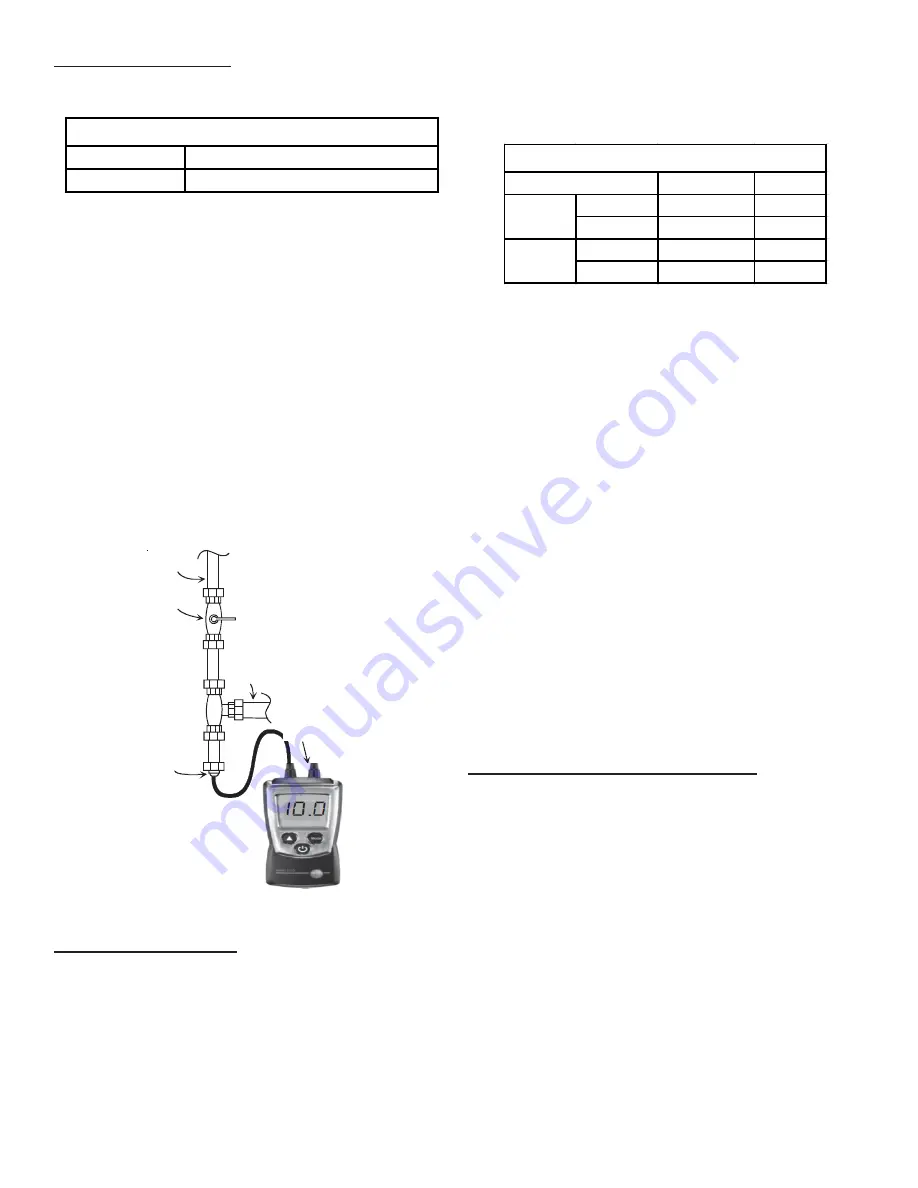
Gas Line
Gas
Shutoff
Valve
Gas Line
To Furnace
Drip Leg Cap
With Fitting
Open To
Atmosphere
Manometer Hose
Manometer
Measuring Inlet Gas Pressure - Alternate Method
Manifold Pressure Check
1 Turn OFF gas to furnace at the manual gas shutoff
valve external to the furnace.
2. Turn off all electrical power to the system.
3. Back outlet pressure test screw (outlet pressure boss)
out one turn (counterclockwise, not more than one
turn).
4. Attach a hose and manometer to the outlet pressure
boss of the valve.
5. Turn ON the gas supply.
6. Turn on power and energize main (M) solenoid. Do
not energize the HI solenoid.
7. Measure gas manifold pressure with burners firing.
Adjust manifold pressure using the Manifold Gas
Pressure table.
Range
Nominal
Low Stage
1.7 - 2.3" w.c.
2.0" w.c.
High Stage
3.2 - 3.8" w.c.
3.5" w.c.
Low Stage
5.7 - 6.3" w.c.
6.0" w.c.
High Stage
9.7 - 10.3" w.c. 10.0" w.c.
Gas
Manifold Gas Pressure
Natural
Propane
Manifold Gas Pressure
8. Remove regulator cover screw from the low (LO)
outlet pressure regulator adjust tower and turn screw
clockwise to increase pressure, or counterclockwise
to decrease pressure.
9. Energize main (M) solenoid as well as the HI terminal.
10. Remove regulator cover screw from the HI outlet
pressure regulator adjust tower and turn screw
clockwise to increase pressure, or counterclockwise
to decrease pressure.
11. Turn off all electrical power and gas supply to the
system.
12. Remove manometer hose from outlet pressure boss.
13. Turn outlet pressure test screw in to seal pressure
port (clockwise, 7 in-lb minimum).
14. Turn on electrical power and gas supply to the system.
15. Turn on system power and energize valve.
16. Using a leak detection solution or soap suds, check
for leaks at pressure boss screw. Bubbles forming
indicate a leak. SHUT OFF GAS AND FIX ALL LEAKS
IMMEDIATELY.
NOTE:
For Natural gas to LP gas conversion, Conversion
Kit “LPM-08” must be used. Consult your dealer for appro-
priate conversion kit(s)
Gas BTU Input Check (Natural Gas Only)
To measure the gas input use a gas meter and proceed as
follows:
1. Turn off gas supply to all other appliances except the
unit.
2. With the unit operating, time the smallest dial on the
meter for one complete revolution. If this is a 2 cubic
foot dial, divide the seconds by 2; if it is a 1 cubic foot
dial, use the seconds as is. This gives the seconds
per cubic foot of gas being delivered to the unit.
3. INPUT=GAS HTG VALUE x 3600 / SEC. PER CUBIC
FOOT
Example:
Natural gas with a heating value of 1000 BTU per
cubic foot and 36 seconds per cubic foot as determined by
Step 2, then:
Input = 1000 x 3600 / 36 = 100,000 BTU per Hour.
NOTE:
BTU content of the gas should be obtained
from the gas supplier. This measured input must not
be greater than shown on the unit rating plate.
Содержание APG 16 M Series
Страница 28: ...28 CFM OUTPUT AND DIP SWITCH SETTINGS...
Страница 31: ...31 THIS PAGE IS LEFT INTENTIONALLY BLANK...


