background image

15

2.

Upflow 

and 

Counterflow 

units

.

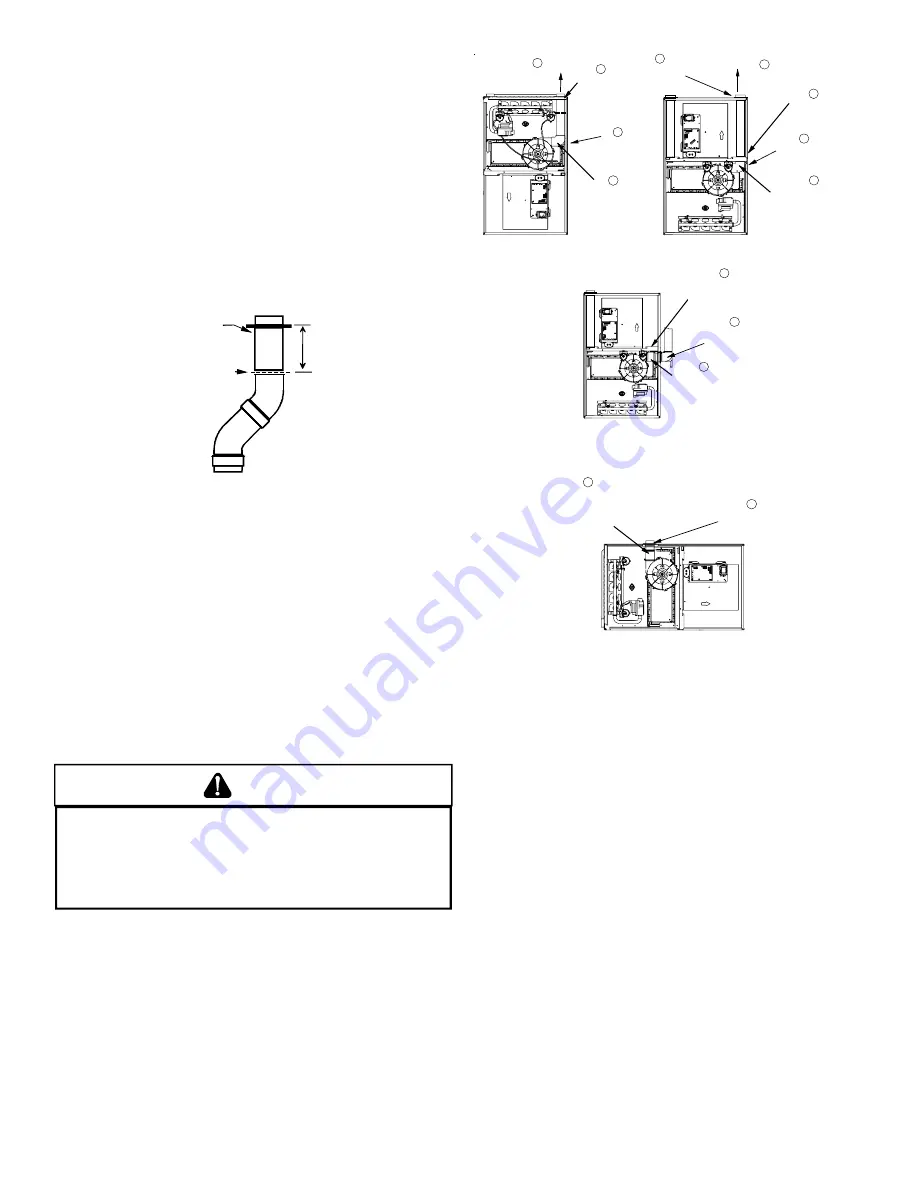
Loosen the worm gear hose clamps on the rubber elbow
and detach it from both the induced draft blower and the vent/
flue pipe.

3.

Upflow 

and 

Counterflow 

units

.

Remove the vent/flue pipe from the furnace.

4.

Cut the vent/flue pipe 3.75 inches from the flanged end of
the pipe. 

See Vent/Flue Pipe Cuts figure.

 The section of pipe

attached to the coupling will reach through the side panel to
the induced draft blower. Discard remaining pipe and elbows.

Counterflow 

units.

Cut the vent/flue pipe 3.75 inches from the blower deck
coupling. 

See Vent/Flue Pipe Cuts figure.

 Save vent/flue pipe

attached to blower deck coupling for use in the alternate
location. Discard remaining pipe and elbows.

FLANGE

CUT


HERE

3.75"

Vent/Flue Pipe Cuts

5.

Remove plastic plug from alternate vent/flue location.
Relocate and install plug in standard vent/flue location (top
cover).

Counterflow

 units.

Remove plastic plug from alternate vent/flue location.
Relocate and install plug in standard vent/flue location
(basepan).  Plug remaining hole in blower deck with plastic
plug included in the drain kit bag.

6.

Upflow 

and 

Counterflow 

units

.

Insert cut section of vent/flue pipe and coupling into alternate
vent/flue location.  Using a rubber coupling and worm gear
hose clamps from the drain kit bag, attach the vent/flue pipe
and coupling to the induced draft blower.  Secure the coupling
to the cabinet using the screws removed in step 1 or with
field-supplied 3/8”  #8 self drilling screws.

WARNING

T

HE RUBBER ELBOW IS NOT DESIGNED TO SUPPORT A LOAD.  

W

HEN THE

RUBBER ELBOW IS MOUNTED EXTERNALLY TO THE FURNACE CABINET,

EXTREME CARE MUST BE TAKEN TO ADEQUATELY SUPPORT FIELD-SUPPLIED

VENT/FLUE PIPING, AS DAMAGE CAN RESULT IN LEAKS CAUSING BODILY

INJURY OR DEATH DUE TO EXPOSURE TO FLUE GASES, INCLUDING CARBON

MONOXIDE.

7.

Upflow 

and 

Counterflow 

units

.

For 

upright installations

, externally mount the rubber elbow

to the vent/flue coupling using a worm gear hose clamp.
Secure field supplied vent/flue piping to the rubber elbow
using a worm gear hose clamp.  

NOTE:

  Use of the alternate

vent/flue location for upright installations, requires the drain
trap be installed on the same side of the unit as the flue pipe.

8.

Upflow 

and 

Counterflow 

units

.

For


horizontal installations

, externally secure the field-

supplied vent/flue pipe directly to the vent/flue coupling using
a PVC or ABS coupling or elbow.

5

ADDITIONAL PLUG

FROM DRAIN KIT

7

EXTERNALLY

 MOUNT

RUBBER ELBOW

6

SECURE TO

ID BLOWER WITH

RUBBER COUPLING

AND HOSE

CLAMPS

COUNTERFLOW/UPRIGHT

(UPFLOW SIMILAR)

        UPFLOW 

REMOVE

4 SCREWS

3

REMOVE

PIPE 

2

DETACH RUBBER

ELBOW FROM

 ID BLOWER AND 

VENT/FLUE

PIPE 

1. 

REMOVE

4 SCREWS

2

DETATCH RUBBER

ELBOW FROM

 ID BLOWER AND 

VENT/FLUE

PIPE 

    COUNTERFLOW

3

REMOVE

PIPE 

REMOVE

AND RELOCATE

5

REMOVE

AND RELOCATE

REMOVE

3 SCREWS

1

UPFLOW/HORIZONTAL

(COUNTERFLOW SIMILAR)

6

SECURE TO

ID BLOWER WITH

RUBBER COUPLING

AND HOSE

CLAMPS

6

SECURE TO

CABINET WITH

SCREWS

Alternate Vent/Flue Location

A

LTERNATE

 C

OMBUSTION

 A

IR

 I

NTAKE

 L

OCATION

The alternate combustion air intake location consists of a large, un-
obstructed hole (alternate vent connection is aligned with the In-
duced Draft Blower). To use the alternate combustion air intake lo-
cation, refer to the following steps, and the “Alternate Combustion
Air Intake Location” figure.

NOTE:

  Counterflow unit instructions follow the upflow instructions.

1.

Remove and save the four screws securing the combustion
air intake coupling to the furnace’s top panel (upflow).

Counterflow 

units.

Remove and save the four screws securing the combustion
air intake coupling to the basepan.  Remove an additional
three screws securing the furnace’s internal combustion air
intake pipe to the blower deck.

2.

Remove the combustion air intake coupling and gasket from
the top panel.

Counterflow

 units.

Remove the combustion air intake pipe from the furnace and
cut the pipe at the basepan coupling.  Save the basepan
coupling and gasket from the blower deck coupling for use
in the alternate location.  Discard the remaining pipe.

3.

Remove plastic plug from alternate combustion air intake
location.  Relocate and install plug in standard air intake
location (top cover).

Содержание ACS9

Страница 1: ...Remember it is your responsibility to install the product safely and to know it well enough to be able to instruct a customer in its safe use Safety is a matter of common sense a matter of thinking be...

Страница 2: ...ROPER VENT FLUE AND COMBUSTION AIR PIPING PRACTICES 13 TERMINATION LOCATIONS 13 CANADIAN VENTING REQUIREMENTS 14 STANDARD FURNACE CONNECTIONS 14 ALTERNATE FURNACE CONNECTIONS 14 NON DIRECT VENT SINGLE...

Страница 3: ...ENERAL 30 INTEGRATED CONTROL MODULE 30 PRIMARY LIMIT 30 AUXILIARY LIMIT 30 ROLLOUT LIMIT 30 PRESSURE SWITCHES 30 FLAME SENSOR 30 XVIII Troubleshooting 31 ELECTROSTATIC DISCHARGE ESD PRECAUTIONS 31 DIA...

Страница 4: ...warranty certificate is also supplied with the unit Read the warranty carefully and note what is covered Keep the warranty certificate in a safe location for future reference If additional informatio...

Страница 5: ...Coil Front Cover Drain Port 21 Drain Line Penetrations 22 Drain Trap 23 Blower Door Interlock Switch 24 Capacitor 25 Integrated Control Module with fuse and diagnostic LED 26 24 Volt Thermostat Conne...

Страница 6: ...on are replaced The input rate and temperature rise are set per the furnace rating plate 100 outside air is provided for combustion air requirements during construction Temporary ducting can be used N...

Страница 7: ...d beneath the furnace between the supply air opening and the combustible floor Exposure to contaminated combustion air will result in safety and performance related problems Do not install the furnace...

Страница 8: ...ust be corrected Corrections must be in accordance with the latest edition of the Na tional Fuel Gas Code NFPA 54 ANSI Z223 1 and or CSA B149 In paint removers varnishes hydrochloric acid cements and...

Страница 9: ...rier etc addi tional air may need to be provided using the methods described in 5 3 3 b or 5 3 4 Space Unconfined For purposes of this Code a space whose volume is not less than 50 cubic feet per 1 00...

Страница 10: ...eets the criteria for an unconfined space The total input of all gas utilization equipment installed in the combined space shall be considered in making this determination Each open ing shall have a m...

Страница 11: ...L APPLI AL APPLI AL APPLIC C C C CA A A A ATI TI TI TI TIO O O O ONS CO NS CO NS CO NS CO NS CONSID NSID NSID NSID NSIDERA ERA ERA ERA ERATI TI TI TI TIO O O O ONS NS NS NS NS GENERAL Horizontal appli...

Страница 12: ...e between natural and propane gas High altitude installations may require both a pressure switch and an orifice change These changes are necessary to compensate for the natural reduction in the densit...

Страница 13: ...S AND EXCESSIVE HEAT AS THEY ARE COMBUSTIBLE LIQUIDS AVOID BREATHING CEMENT VAPORS OR CONTACT WITH SKIN AND OR EYES Two or three inch nominal diameter PVC Schedule 40 pipe meet ing ASTM D1785 PVC prim...

Страница 14: ...STALLATIONS On upflow units secure the combustion air intake pipe directly to the air intake coupling On counterflow units secure the combus tion air intake pipe to the air intake coupling using the r...

Страница 15: ...vent flue piping to the rubber elbow using a worm gear hose clamp NOTE Use of the alternate vent flue location for upright installations requires the drain trap be installed on the same side of the un...

Страница 16: ...the wall and solvent cemented to a length of pipe connecting the two couplings The length of pipe should be the wall thickness plus the depth of the socket fittings to be in stalled on the inside and...

Страница 17: ...r tees in each Vent Flue Combustion Air Intake pipe Elbows and or tees used in the terminations must be included when determining the number of elbows in the piping systems If the combustion air intak...

Страница 18: ...nces be tween the exhaust vent and air intake terminations of adjacent units as with the exhaust vent and air intake terminations of a single unit If more than one direct vent furnace is to be install...

Страница 19: ...n port right or left side depending on the intended drain trap mounting 2 Secure HoseAto front cover drain port with a red hose clamp Route hose to rear side panel grommet hole NOTE For left side drai...

Страница 20: ...as follows 1 Remove the rubber plug from the coil front cover drain port Counterflow furnaces Relocate the front cover pressure switch hose connection from the left side pressure tap to the right dow...

Страница 21: ...harness is an integral part of this furnace Field alter ation to comply with electrical codes should not be required Wires are color and number coded for identification purposes Refer to the wiring di...

Страница 22: ...0 Amp maximum at 120 VAC Turn OFF power to the furnace before installing any accessories Follow the humidifier or air cleaner manufacturers instructions for locating mounting grounding and controllin...

Страница 23: ...ro pane gas spring from an appropriate manufacturer s propane gas conversion kit Taps for measuring the gas supply pressure and manifold pressure are provided on the valve The gas valve has a manual O...

Страница 24: ...TO ACCOMMODATE LINE GAS PRESSURE MEASUREMENT Gas Piping Connections CAUTION EDGES OF SHEET METAL HOLES MAY BE SHARP USE GLOVES AS A PRECAUTION WHEN REMOVING HOLE PLUGS DIRECT STANDARD INLET PIPING Whe...

Страница 25: ...tandards of the National Board of Fire Underwriters NBFU Manual 58 For satisfactory operation propane gas pressure must be 11 inch w c at the furnace manifold with all gas appliances in operation Main...

Страница 26: ...or NOTE This furnace is equipped with an ignition device which automatically lights the burner Do not try to light the burner by hand 5 Move the furnace gas valve manual control to the OFF position du...

Страница 27: ...Off Selector Switch Inlet Pressure Tap Side of Valve Outlet Manifold Pressure Tap White Rodgers Model 36F22 1 Turn OFF gas to furnace at the manual gas shutoff valve external to the furnace 2 Connect...

Страница 28: ...gulator preset see control label Consult the appliance rating plate to ensure burner manifold pres sure is as specified If another outlet pressure is required follow these steps 1 Turn OFF all electri...

Страница 29: ...quipped with a multi speed circulator blower This blower provides ease in adjusting blower speeds The Product Data Book applicable to your model provides an airflow table showing the relationship betw...

Страница 30: ...ange tips but they must not be yellow Flames should extend directly outward from the burners without curling floating or lifting off Flames must not impinge on the sides of the heat exchanger firing t...

Страница 31: ...the furnace for 0 20 seconds NOTE If the condition which originally caused the lockout still exists the control will return to lockout Refer to Section XVIII Troubleshooting Diagnostic Chart for aid i...

Страница 32: ...ue pipe system from the induced draft blower 4 Remove the induced draft blower and drain and pressure tap hoses from the recuperator coil front cover 5 Remove the recuperator coil front cover to expos...

Страница 33: ...s List Gas Valve Blower Motor Gas Manifold Blower Wheel Natural Gas Orifice Blower Mounting Bracket Propane Gas Orifice Blower Cutoff Igniter Blower Housing Flame Sensor Capacitor Rollout Limit Switch...

Страница 34: ...pinched or connected improperly Blocked flue and or inlet air pipe blocked drain system or weak induced draft blower Incorrect pressure switch setpoint or malfunctioning switch contacts Loose or impr...

Страница 35: ...section for piping details See rating plate for proper gas pressure 7 7 FLASHES Flame sensor is coated oxidized Flame sensor incorrectly positioned in burner flame Lazy burner flame due to improper ga...

Страница 36: ...IER FLAME SENSOR 115 VAC TRANSFORMER 40 VA 24 VAC NO C NO C GND CONTR OL LIMIT PRIM AR Y AUT OR ESET SINGLECONTROLO N45KBTU LIMITCONTROL S MANUALRESETROL LOUT RO1 5 RO2 11 HLO 1 HLI 7 PS 10 MVC 9 MV 1...

Страница 37: ...H FLAME SENSOR FRONT COVER PRESSURE SWITCH SINGL ECO N TR OLON45KBT U NO C GY BK PLUG CONNECTION FIELD SPLICE SWITCH TEMP OR 24V THERMOSTAT CONNECTIONS BU GN GND 115 VAC 24 VAC BLOWER COMPARTMENT DOO...

Страница 38: ...2004 2006 Goodman Company L P is a trademark of Maytag Corporation and is used under license to Goodman Company L P All rights reserved 2550 North Loop West Suite 400 Houston TX 77092 www amana hac c...

Отзывы: